
The Core Concepts: Understanding Dimensions, Tolerances, and Fits
In mechanical assembly design, parts must interact with absolute precision. No manufacturing process can produce an exact dimension every single time, which is why understanding engineering tolerances and how components merge is critical to your project’s success.
Choosing the correct relationship between mating parts ensures that a shaft rotates smoothly in a bearing or locks permanently into a housing. Managing these microscopic variations prevents assembly failures, premature wear, and skyrocketing CNC machining costs.
Key Engineering Terminology: Nominal Size vs. Actual Size
To design functional assemblies, you must distinguish between design intent and manufacturing reality.
- Nominal Size: The theoretical target dimension specified on your engineering drawings (e.g., a 20 mm shaft). It serves as the baseline for calculation.
- Actual Size: The final measured dimension of the physical part after production.
- Tolerance Zone: The permissible variation variation between the maximum and minimum allowable limits.
Decoding Alphanumeric Fit Callouts (H7/g6)
Standardized limits and fits rely on the ISO 286 standard to communicate precise assembly requirements globally using a simple alphanumeric code, such as H7/g6.
| Code Component | Meaning | Description |
|---|---|---|
| Letter Case | Capital vs. Lowercase | Uppercase letters (e.g., H) designate hole dimensions. Lowercase letters (e.g., g) designate shaft dimensions. |
| Letter Position | Fundamental Deviation | Indicates the position of the tolerance zone relative to the nominal size (how far it deviates from baseline zero). |
| IT Number | International Tolerance Grade | Defines the size of the tolerance zone. Lower numbers (e.g., 6, 7) mean tighter tolerances and higher precision. |
For example, an H7 hole combined with a g6 shaft creates a standard sliding fit, ensuring the shaft can rotate freely without excessive wobble.
The Interdependence of Tolerance and Fit
A fit is determined entirely by the relationship between the tolerance zones of two mating parts. You cannot choose a fit class without directly constraining your manufacturing limits.
- Tightening your tolerances shrinks the variance in your fit, leading to highly predictable assemblies.
- Loosening tolerances reduces production costs but creates a wider variance between the tightest and loosest possible assembly conditions.
Understanding Upper and Lower Deviations
Deviations dictate the boundaries of your tolerance zone relative to the nominal baseline.
- Upper Deviation: The difference between the maximum limit of size and the nominal size.
- Lower Deviation: The difference between the minimum limit of size and the nominal size.
For a hole, reaching the maximum material condition (MMC) occurs at its lowest allowable size limit. For a shaft, MMC occurs at its upper deviation limit. Properly calculating these deviations ensures that your parts assemble perfectly under every manufacturing scenario.
Clearance Fits: When Parts Need to Move

When your mechanical assembly design requires components to rotate, slide, or pivot freely without binding, you need a clearance fit. The fundamental goal here is to guarantee unrestricted motion. In a clearance fit, the hole is always machined larger than the shaft, leaving a deliberate air gap or tolerance zone between the mating parts. This gap accommodates lubrication, thermal expansion, and minor misalignments, ensuring smooth operation under real-world conditions.
Key Subtypes: From Loose Running to Sliding Fits
Depending on how much precision your assembly demands, clearance fits are divided into several distinct classes:
- Loose Running Fits: These offer the largest tolerance zone. They are ideal for applications where accuracy is secondary, and dust, debris, or thermal expansion are major concerns.
- Free Running Fits: Used where speeds are high and heavy lubrication is necessary, allowing components to rotate with minimal friction.
- Close Running Fits: Designed for smaller clearances, offering good cutting-edge guidance for parts turning at moderate speeds.
- Sliding Fits: The tightest of the clearance fits. Parts can slide or rotate, but they maintain high precision and cannot move sideways.
Real-World Applications in Bearings and Hinges
Clearance fits are the backbone of moving machinery. You will find them everywhere from simple mechanical hinges to high-speed rotational components. For instance, our custom ratchet wheels rely on precise clearance limits to index and rotate freely without catching. Similarly, sleeve bearings, guide bushings, and sliding shafts in manufacturing equipment all require specific CNC machining tolerances to function without seizing up.
Calculating Clearance Limits for Smooth Rotation
To achieve a perfect clearance fit, engineers must calculate the limits of size using the maximum material condition (MMC). This ensures that even when the shaft is at its largest allowable size and the hole is at its smallest, a minimum clearance remains.
| Fit Type | Minimum Clearance | Maximum Clearance | Primary Function |
|---|---|---|---|
| Loose Running | Large | Very Large | Resists corrosion, debris, and heavy thermal growth |
| Free Running | Moderate | Large | High-speed rotation with continuous lubrication |
| Sliding Fit | Zero (Targeted) | Small | High-precision linear or rotational guidance |
By strictly adhering to standard engineering tolerances like the ISO 286 standard or ANSI B4.1 fit classes, you can establish the exact upper and lower deviations required for your shafts and holes, guaranteeing a reliable, repeatable fit every single time.
Interference Fits: Creating Permanent Bonds
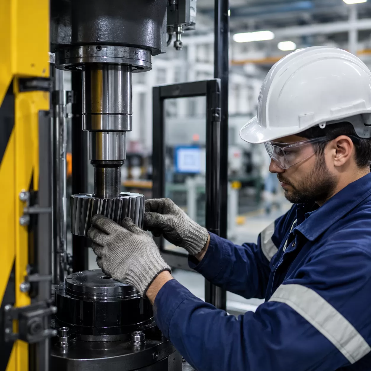
When your design requires two parts to act as a single, solid unit without the use of fasteners or adhesives, an interference fit is the go-to solution. In this setup, the shaft diameter is intentionally larger than the hole diameter, creating a high-friction bond that prevents any relative motion between the components.
Functional Goals for Rigid Locking
The primary objective of an interference fit is to achieve a permanent or semi-permanent connection. By utilizing tight engineering tolerances, we ensure the parts remain joined even under heavy torque or constant vibration. This is critical for maintaining the integrity of a high-speed shaft where even a micro-millimeter of slippage could lead to mechanical failure.
Press and Force Fit Subtypes
Depending on the level of friction required, we categorize these fits into specific subtypes:
- Press Fit: Requires moderate force to assemble, typically achieved using an arbor press.
- Force Fit: A much tighter tolerance that requires significant hydraulic pressure or thermal assistance.
- Tight Fit: Used for assemblies that must stay put during operation but might need to be disassembled with specialized tools later.
Assembly Methods: Thermal Expansion and Arbor Presses
Getting a larger shaft into a smaller hole requires more than just brute force. We often utilize thermal expansion—heating the component with the hole or freezing the shaft—to temporarily change the dimensions for easier insertion. For standard mechanical assembly, hydraulic arbor presses provide the controlled force necessary to overcome the maximum material condition (MMC) of the mating parts without damaging the surfaces.
Applications in Gears and Tool Spindles
Interference fits are the backbone of high-stress mechanical systems. Because they eliminate the need for keys or pins, they are perfect for:
- Gears and Pulleys: Firmly locked onto shafts to transmit high torque.
- Tool Spindles: Ensuring high-precision rotation in CNC machinery without any runout.
- Bearing Races: Seated firmly within housings to prevent the outer ring from spinning.
- Bushings: Pressed into place to provide a stable, wear-resistant surface for rotating parts.
Our expertise in CNC shaft machining allows us to hit these precise interference limits consistently, ensuring your assemblies stay locked tight under the most demanding conditions.
Transition Fits: The High-Precision Middle Ground

When your mechanical assembly design requires exact alignment without the permanent locking of a press fit, transition fits offer the ideal middle ground. Depending on the actual manufacturing sizes of the mating parts, this type of fit can create either a slight clearance or a minor interference.
Functional Goals for Accurate Alignment
The primary objective of a transition fit is to guarantee precise coaxial alignment. It eliminates unwanted play between components while ensuring the mating parts can still be assembled or disassembled without destroying the machinery. This balance makes it indispensable for components that must remain perfectly centered during operation but require occasional maintenance.
Light and Medium Push Fit Subtypes
Transition fits are generally classified by the amount of effort required for assembly:
- Light Push Fits: These exhibit minimal interference and a small amount of clearance. Parts can usually be assembled or adjusted by hand or with light hand tools.
- Medium Push Fits: These lean closer to the interference side. They provide higher positional accuracy and typically require a rubber mallet or light arbor press to seat the components properly.
Applications in Dowel Pins and Ball Bearings
You will frequently encounter transition fits in high-precision setups. They are the industry standard for positioning mating faces with mating dowel pins, securing precision transmission components like shafts and gears, and mounting ball bearings into housings where shaft concentricity is critical.
Balancing Disassembly Needs with Precision
Choosing a transition fit comes down to balancing the tolerance zone of your mating parts. By carefully managing the maximum material condition (MMC), you achieve tight, vibration-resistant alignment during operation while maintaining the flexibility to dismantle the setup for servicing without damaging the CNC machining tolerances of your components.
Hole-Basis vs. Shaft-Basis Systems: Choosing Your Fit Standard
When designing a mechanical assembly design, you must decide whether to base your limits and fits on the hole or the shaft. Standardizing this choice keeps your manufacturing organized and prevents skyrocketing production costs.
Why the Hole-Basis System is the Global Standard
In the vast majority of engineering applications, we use the hole-basis system. In this system, the hole’s nominal size remains constant (at the zero line, designated as ‘H’), and we alter the shaft’s size to achieve a clearance, transition, or press fit.
- Tooling Economy: Changing a shaft diameter on a lathe is simple. Changing a hole diameter requires entirely different drill bits, reamers, or broaches.
- Standardization: It is much cheaper to adjust CNC machining tolerances on an external profile than to buy specialized internal cutting tools for every minor design tweak.
When to Opt for a Shaft-Basis System
While less common, the shaft-basis system sets the shaft at a constant size (designated as ‘h’) and varies the hole dimension. You should opt for this system when using standard, off-the-shelf components where the outer diameter cannot be easily altered. For instance, if you are mounting multiple components onto a pre-ground precision bar or installing standard commercial lock nut seats, modifying the shaft is impractical. In these scenarios, adjusting the internal tolerances of the mating parts is the only logical choice.
Impact on Tooling and CNC Machining Costs
Your choice of system directly impacts your bottom line. Sticking to the hole-basis system allows machine shops to utilize standard plug gauges and stock reamers, keeping your CNC machining tolerances tight without adding custom tooling surcharges. Straying from this standard without a specific functional reason introduces unnecessary manufacturing complexity and increases cycle times on the shop floor.
Standardizing with ISO 286 and ANSI B4.1
To ensure global interchangeability, always reference established international standards. The ISO 286 standard uses metric alphanumeric callouts (like H7/g6) to define the exact boundaries of a tolerance zone. For imperial projects, ANSI B4.1 fit classes (such as RC, LC, LT, and FN fits) provide the equivalent standardized limits. Utilizing these frameworks guarantees that your parts will fit perfectly, whether they are machined locally or overseas.
How to Choose the Right Fits in Engineering for Your Project
Selecting the right mechanical fit determines how your components interact, move, and wear over time. Making the wrong choice leads to premature part failure, difficult assembly, or skyrocketing production costs.
1. Define Functional Requirements: Rotation vs. Alignment
First, establish exactly what the assembly needs to do.
- For continuous rotation or sliding: Opt for a clearance fit. This ensures moving parts have enough breathing room to operate without seizing.
- For precise alignment without permanent locking: A transition fit offers accurate positioning with the ability to disassemble the components when needed.
- For rigid, load-bearing bonds: An interference fit creates a semi-permanent or permanent mechanical lock capable of transmitting torque without keys or splines.
2. Evaluate Thermal Expansion and Vibration Factors
Operating environments heavily influence how a fit performs in the field.
Fit Selection Matrix: Environmental Factors
| Environmental Factor | Impact on the Fit | Engineering Solution |
|---|---|---|
| High Operating Temperatures | Thermal expansion narrows clearance gaps or intensifies press fits. | Increase initial clearance or use materials with matching expansion coefficients like carbon steel CNC machining to maintain stability. |
| Heavy Vibrations & Shocks | Causes clearance fits to rattle and transition fits to loosen over time. | Upgrade to a heavier interference fit or integrate secondary locking mechanisms. |
| Corrosive Environments | Promotes rust, seizing, or fretting corrosion between tight tolerances. | Select corrosion-resistant materials such as stainless steel parts and apply proper surface lubrication. |
3. Analyze Manufacturing Processes and Tolerance Grades
Your manufacturing method dictates the tolerance grades you can realistically achieve. Tight tolerances require precise CNC turning and grinding, which naturally increases production time. Standardizing your designs around standard ISO or ANSI tolerance zones ensures your parts remain manufacturable on standard production lines without requiring specialized, ultra-high-precision machinery for every single run.
4. The Economics of Engineering Fits: Precision vs. Cost
In manufacturing, tighter tolerances equal higher costs. Aim for the loosest possible fit that still safely meets the functional requirements of your product.
- High Precision (IT6 – IT7): Best reserved for critical mating surfaces like bearings, tool spindles, and high-speed shafts.
- Standard Precision (IT8 – IT11): Ideal for general machinery, structural brackets, and clearance holes where absolute perfection isn’t necessary for performance.
Manufacturing Precision Fits with HXCNC
Achieving the perfect mechanical assembly design requires a manufacturing partner who understands the strict physics of limits and fits. At HXCNC, we specialize in turning your complex engineering tolerances into flawlessly executed physical parts. Whether your project demands tight clearances or rigid press fits, our facility is optimized to deliver consistent, high-precision results every single time.
Achieving IT6 and IT7 Tolerance Levels
We regularly hit IT6 and IT7 international tolerance grades, which are critical for high-performance applications.
- IT6 Tolerances: Ideal for precise cylindrical fits, ensuring smooth movement in high-speed components.
- IT7 Tolerances: The industry standard for reliable production fits, offering an excellent balance between precision and manufacturing efficiency.
Expert DFM Advice for Your Engineering Drawings
Before we spin up our machines, our engineering team reviews your CAD files and blueprints. We provide practical Design for Manufacturability (DFM) feedback to ensure your hole-basis or shaft-basis callouts are optimized for production. By catching potential tolerance stacks early, we help you avoid costly reworks and assembly headaches down the line. If your assembly requires extreme dimensional accuracy, we often integrate specialized CNC grinding to achieve ultra-precise surface finishes and tight micron-level limits.
How We Optimize CNC Milling and Turning for Perfect Fits
We don’t leave precision to chance. Our shop floors leverage advanced CNC machining tolerances and specialized cutting strategies to maintain absolute control over every workpiece:
- State-of-the-Art CNC Lathes & Mills: Equipped with live tooling and rigid spindles to prevent deflection.
- Real-Time In-Process Inspection: High-resolution probing systems verify dimensions during the machining cycle.
- Thermal Stabilization: Controlled environment machining to prevent material expansion from altering critical dimensions.
By combining advanced CNC milling and turning with rigorous quality control, we ensure that every shaft, hole, and housing matches your exact alphanumeric fit callouts perfectly.
Frequently Asked Questions About Engineering Fits
What is the most common engineering fit?
The most common engineering fit used across manufacturing is the clearance fit, specifically utilizing the hole-basis H7/g6 or H7/h6 classification. This combination ensures that parts can rotate or slide freely without binding, which is essential for standard mechanical assembly design.
How do I choose between a clearance and transition fit?
Choose a clearance fit when your components require unrestricted relative motion, such as axles or cnc precision transmission components. Opt for a transition fit when you need precise alignment and the ability to dismantle the assembly without damaging the parts, like positioning dowel pins.
What does H7/h6 mean in engineering?
In the ISO 286 standard, H7/h6 defines a specific tolerance zone combination for high-precision locational clearance fits:
- H7: Represents the hole tolerance (capital letter). The ‘H’ means the lower deviation starts at the nominal size, and ‘7’ is the IT grade.
- h6: Represents the shaft tolerance (lowercase letter). The ‘h’ means the upper deviation tops out at the nominal size, and ‘6’ indicates a tighter manufacturing tolerance.
How does temperature affect interference fits?
Temperature directly changes the limits and fits of an assembly through thermal expansion and contraction. Heating the outer component (hole) or freezing the inner component (shaft) temporarily alters the physical dimensions, allowing a tight press fit to slip together effortlessly before locking permanently as temperatures equalize.
Can I achieve interference fits with 3D printing vs CNC?
While 3D printing can handle loose fits, CNC machining tolerances are mandatory for successful interference fits. 3D printing typically lacks the micron-level positional accuracy required for a rigid force fit, often resulting in loose joints or split plastic layers. Precision CNC turning and milling deliver the exact dimensional control needed for repeatable mechanical bonds.