
Product Category
OIP — 001 to 011
Optical &
Instrumentation
Precision Parts
11 product lines for optical systems, metrology instruments, scientific apparatus, machine vision, and precision sensing — where dimensional stability, surface flatness, and material thermal behaviour determine measurement accuracy rather than just mechanical function.
Flatness ±0.003 mm on mounting and reference surfaces
Thermal stability — Invar36 (CTE 1.2 ppm/K) stocked as standard
Non-magnetic materials for magnetically sensitive optical systems
CMM full report on every optical mounting part
📐
±0.003mm
Surface Flatness
Optical platform and instrument mounting faces
🌡
1.2ppm/K
Invar CTE
Ultra-low expansion for thermal-critical mounts
◎
±0.005mm
Bore Tolerance
Lens seat and sensor bore fits
🔬
Ra ≤0.4μm
Surface Finish
Optical contact and reference surfaces
🧲
Non-Magnetic · Clean-Room Ready
Material & Delivery Options
Al6061, Invar36, SS304, Titanium — all non-magnetic. Clean-room packaging available for sensitive optical assemblies.
11
Product Lines
±0.003mm
Flatness
Invar36
Thermal Stable
Ra ≤0.4μm
Surface Finish
24hr
Quote Turnaround
Lens Mounting Seats ✦
Optical Mounting Brackets ✦
Optical Platform Connector Blocks ✦
Precision Adjustment Seats ✦
Fine Adjustment Mounts ✦
Instrument Mounting Plates ✦
Inspection Probe Brackets ✦
Sensor Seats ✦
Locating Rings ✦
High-Stability Mounting Bases ✦
Precision Housing Skeleton Parts ✦
Lens Mounting Seats ✦
Optical Mounting Brackets ✦
Optical Platform Connector Blocks ✦
Precision Adjustment Seats ✦
Fine Adjustment Mounts ✦
Instrument Mounting Plates ✦
Inspection Probe Brackets ✦
Sensor Seats ✦
Locating Rings ✦
High-Stability Mounting Bases ✦
Precision Housing Skeleton Parts ✦
Full Product Range
11 Optical & Instrumentation
Precision Product Lines
Select a category tab · All parts machined to drawing · MOQ 1 piece · CMM inspection standard
Product Categories
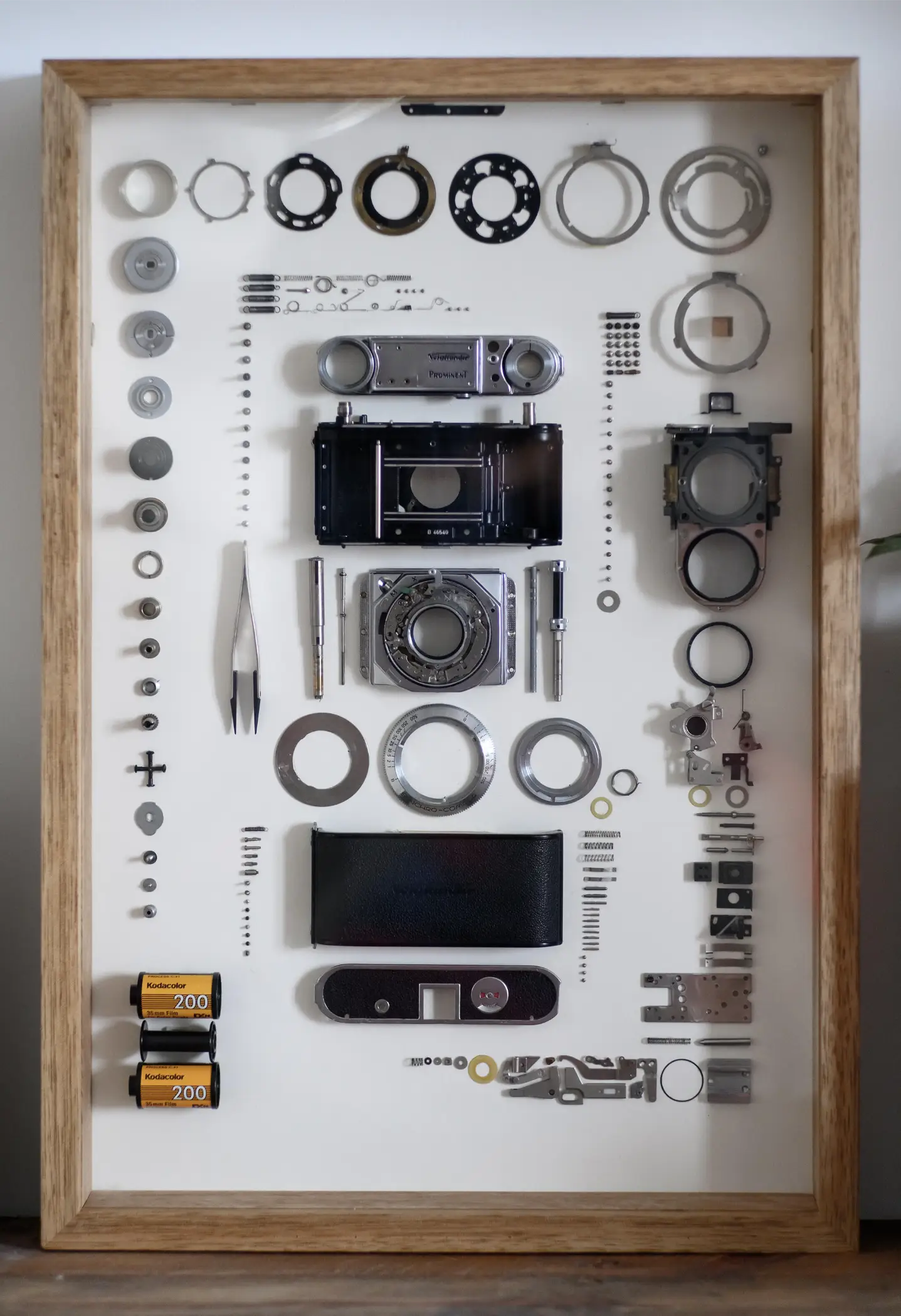
Lens mounting seats, optical component mounting brackets, and optical platform connector blocks — the primary interface hardware between optical elements and the instrument structure. Lens seat bore diameter tolerance ±0.005 mm; bore perpendicularity to mounting face ≤0.005 mm. Platform connector blocks machined with flatness ±0.003 mm on all mating faces. All optical mounting parts supplied in Al6061 (hard-anodized for stray light absorption), Invar36 (thermal stability), or SS304 (non-magnetic, clean environments).
OIP-001
LENS & OPTICAL MOUNTS / 001 — FEATURED
Lens Mounting Seats
Precision cylindrical lens seats for single optical elements, doublets, and cemented lens groups. Inner bore machined to H6 tolerance (±0.005 mm) with bore-to-face perpendicularity ≤0.005 mm — directly determining optical axis tilt and decenter. Retaining ring thread machined in the same setup as the bore to ensure thread axis collinearity with optical axis. Seat depth controlled to ±0.01 mm for back focal distance accuracy. Available in black-anodized Al6061 (stray light absorption), Invar36 (thermal focus stability), and SS304 (clean environments). Custom flange patterns for system integration.
Al6061 (Black Anodize) · Invar36 · SS304
Get Quote

OIP-002
LENS & OPTICAL MOUNTS / 002
Optical Mounting Brackets
L-brackets, post mounts, and kinematic mounting brackets for mirrors, beamsplitters, polarisers, and optical filters on optical tables. Kinematic three-point contact option for repeatable component repositioning. Mounting face flatness ±0.004 mm; post bore H7. Black anodize standard for stray light control.
Al6061 · Invar · SS304Get Quote

OIP-003
LENS & OPTICAL MOUNTS / 003
Optical Platform Connector Blocks
Interface blocks connecting sub-assemblies within optical instruments — between breadboard sections, between tube assemblies, and between instrument chassis and optical bench. All six faces ground to flatness ±0.003 mm. Perpendicularity between faces ≤0.005 mm. Supplied with CMM report on all faces.
Al6061 · Invar36 · SS304Get Quote

Precision adjustment seats and fine-adjustment mounting components for optical alignment systems, beam steering assemblies, and vernier positioning stages. Adjustment screw thread fit quality directly determines backlash and positioning resolution — differential screw and micrometer-head thread bores machined to 4H/6H tolerance. Adjustment range and locking geometry machined to drawing. All parts designed for minimum adjustment hysteresis through controlled surface contact geometry.
OIP-004
ADJUSTMENT & POSITIONING / 004 — FEATURED
Precision Adjustment Seats
Tilt and tip-tilt adjustment seat bodies for optical mounts, beam-steering mirrors, and alignment fixtures. Pivot contact geometry precision-machined to reduce stick-slip and increase adjustment sensitivity. Adjustment screw seat bore machined to 4H/6H thread tolerance for minimum backlash engagement with fine-pitch differential screws. Kinematic ball-and-flat contact surfaces ground to Ra ≤0.4 μm. Pivot-to-optical-axis distance held to ±0.02 mm for predictable angular sensitivity. Locking set-screw positions sized to prevent elastic deformation of mounting face when locked. Supplied with sub-assembly adjustment range verification measurement.
Al6061 · SS304 · Invar36 · BronzeGet Quote

OIP-009
ADJUSTMENT & POSITIONING / 009
Precision Locating Rings
Optical tube locating rings, element spacer rings, and precision spacing collars. Bore-to-face perpendicularity ≤0.003 mm; face flatness ±0.003 mm. Thickness tolerance ±0.005 mm for BFD control in multi-element systems. Lapped faces available.
Al6061 · SS304 · Invar · TiGet Quote
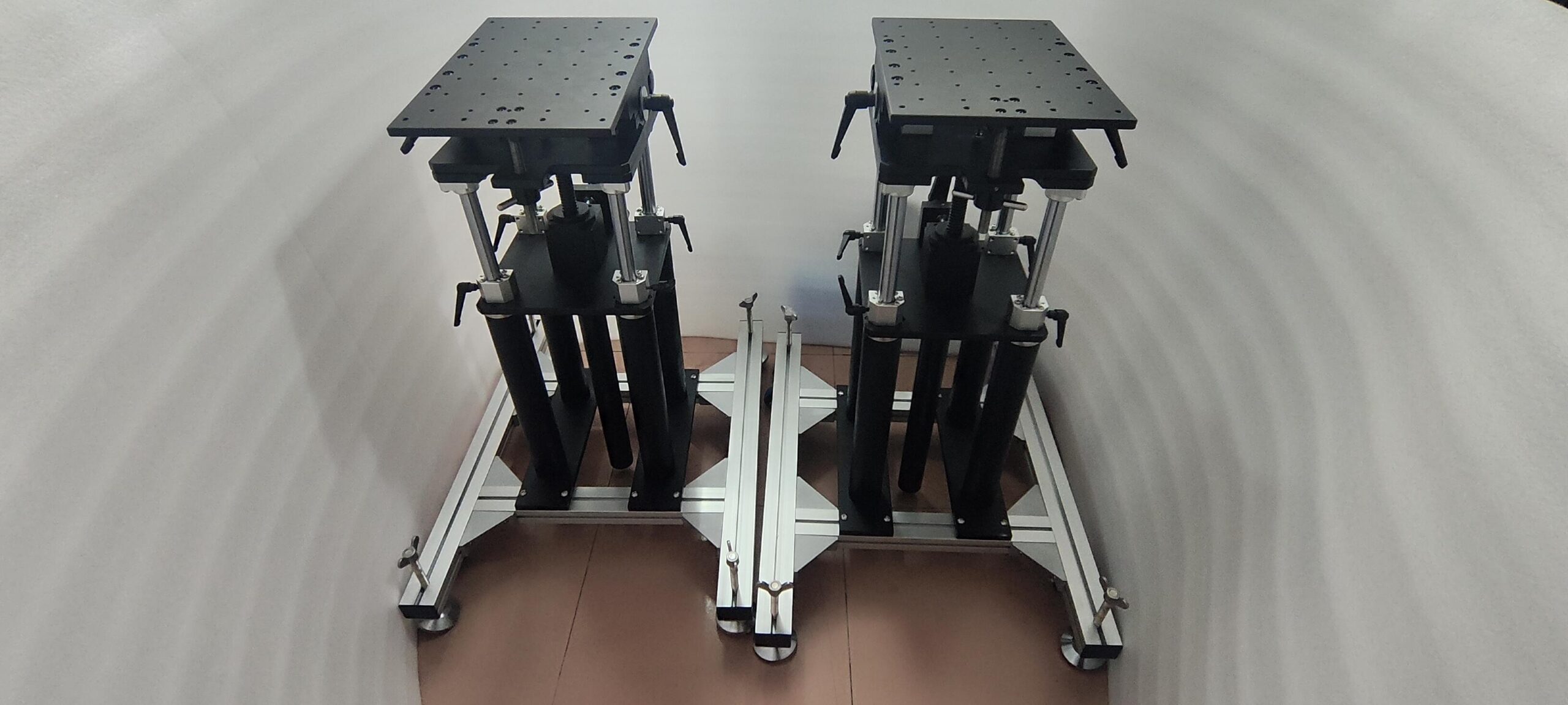
Instrument mounting plates for reference attachment of measurement devices, inspection probe bracket bodies for CMM, vision system, and non-contact sensor probes, and sensor mounting seats for distance, displacement, force, and optical sensors. Mounting hole patterns positioned to ±0.008 mm. Probe bracket repeatability — kinematic design with ±0.005 mm relocation accuracy. All parts supplied with CMM dimensional report and, where specified, non-magnetic certification for use near magnetic sensors.
OIP-006
INSTRUMENT MOUNTING / 006 — FEATURED
Instrument Mounting Plates
High-flatness mounting plates for attaching measuring instruments, interferometers, autocollimators, and optical modules to instrument chassis, vibration-isolation tables, and granite surface plates. Top surface flatness ±0.003 mm after stress-relieved machining and grinding. Fastener pattern position tolerance ±0.008 mm. Stress-relieved Al6061-T651 plate eliminates post-machining bow and warp — critical for plates larger than 200 mm. Invar36 for applications where thermal dimensional change must be suppressed across the operating temperature range. Through-holes counter-bored flush to prevent fastener head protrusion above mounting surface. Supplied with CMM flatness map report.
Al6061-T651 · Invar36 · SS304 · Granite (ref)Get Quote

OIP-008
INSTRUMENT MOUNTING / 008
Sensor Mounting Seats
Precision mounting seats for eddy current, capacitive, laser triangulation, and interferometric displacement sensors. Sensor bore tolerance ±0.005 mm; mounting face perpendicularity ≤0.004 mm for accurate stand-off distance. Magnetic shielding geometry available for Hall-effect and inductive sensors.
Al · SS304 · PEEK · Non-magneticGet Quote
Manufacturing Capability
What Optical & Instrument Parts
Demand from Precision Machining
±0.003mm
Flatness
1.2 ppm/K
Invar CTE
H6 Bore
Lens Seat
Non-Mag
Material
📐
Optical-Grade Flatness — ±0.003 mm on Reference Faces
Optical mounting surfaces are reference faces — any deviation from flatness directly tilts the optical element and contributes to wavefront error in the system. Mounting faces machined and ground to ±0.003 mm flatness, verified by CMM surface scan with deviation colour map. Not measured by feeler gauge — scanned by CMM and reported.
±0.003mm flatnessCMM colour mapGround + measured
🌡
Invar36 Machining — Thermal Stability Where It Matters
Invar36 (CTE 1.2 ppm/K) stocked and machined in-house as standard. For a 200 mm optical base, Invar shifts 0.24 μm per °C vs 4.6 μm per °C for aluminium — 19× better thermal stability. We understand Invar's machining characteristics (higher cutting force, work-hardening tendency) and apply dedicated parameters to achieve surface finish Ra ≤0.4 μm without rework.
Invar36 in stockRa ≤0.4μmDedicated protocol
◎
Lens Seat Bore & Perpendicularity — H6 + ≤0.005 mm
Lens seat bore diameter H6 tolerance with bore-to-face perpendicularity ≤0.005 mm — machined in the same setup to guarantee axis collinearity. Retaining ring thread bore machined in the same operation as the lens bore. These three features in one setup is the only way to guarantee mutual perpendicularity without re-fixture error.
H6 bore tolerancePerp. ≤0.005mmOne-setup guarantee
🧲
Non-Magnetic Materials — Every Optical Part Standard
Al6061, Invar36, SS304, and titanium Grade 2 are all non-ferromagnetic — safe for use near Hall effect sensors, magnetometers, and optical systems with magnetic components. We do not substitute SS430 or other magnetic stainless grades even when they are available at lower cost. Non-magnetic compliance confirmed by permeability check on SS304 material lots.
Al / Invar / SS304 / TiNon-ferromagneticPermeability checked
📊
CMM Flatness Map — Not Just a Dimensional Check
Optical mounting surfaces cannot be characterised by a single flatness callout measurement — the shape of the surface deviation matters. We scan reference faces with CMM and produce a flatness deviation colour map showing the actual surface form. Customers use this to orient the part in their optical system to minimise wavefront error contribution.
Surface scan CMMDeviation colour mapForm characterised
🔗
Kinematic Design Capability for Repeatable Positioning
Kinematic three-groove and ball-flat-vee mounts machined to design geometry for repeatable component relocation to ±0.005 mm without realignment. We understand the contact mechanics of kinematic coupling and machine groove width, depth, and angle to maintain the constraint count at exactly 6 DOF — preventing over-constraint distortion.
±0.005mm relocation6-DOF constraintGroove geometry
Precision Specifications
Tolerances & Material Properties — Optical & Instrument Parts
📐
Achievable Tolerances by Feature
Mounting Flatness
±0.003 mm
Lens Bore H6
±0.005 mm
Bore Perpendicularity
≤0.005 mm
Hole Pattern Pos.
±0.008 mm
Spacer Thickness
±0.005 mm
Face Perpendicularity
≤0.003 mm
Surface Finish Ra
≤0.4 μm
Kinematic Reloc.
±0.005 mm
🌡
Thermal Stability Comparison
Invar 36 CTE
1.2 ppm/K
Best thermal stability for optical bases. 200mm base shifts 0.24 μm per °C.
Al6061 CTE
23.6 ppm/K
Standard lightweight option. 200mm base shifts 4.7 μm per °C. Use T651 plate.
SS304 CTE
17.2 ppm/K
Non-magnetic stainless. Good corrosion resistance for clean/humid environments.
Ti Grade 2 CTE
8.6 ppm/K
Intermediate thermal stability, light weight, non-magnetic. Used for compact mounts.
Quality Standard
ISO 9001
Full CMM flatness map and dimensional report on all optical mounting parts.
Magnetic Property
Non-Mag
All standard materials verified non-ferromagnetic. Permeability checked on SS304 lots.
Material Selection
Materials for Optical & Instrumentation Parts
Material selection in optical mounts is not about strength — it's about thermal stability, non-magnetic properties, and surface treatability.
MAT / 01
Invar 36
CTE 1.2 ppm/K · UNS K93600 · Non-magnetic
Best choice where thermal dimensional stability defines instrument accuracy. For critical optical bases, interferometer frames, and long-distance reference structures. 19× less thermal expansion than aluminium.
MAT / 02
Al6061-T651
CTE 23.6 ppm/K · T651 Stress-Relieved · Anodizable
Standard optical mount material — lightweight, machinable, and anodizable (black anodize for stray light control, hard anodize for wear). T651 plate avoids post-machining distortion in large plates. Most lens seats, brackets, and connector blocks.
MAT / 03
SS304 (Non-Magnetic)
CTE 17.2 ppm/K · Non-ferromagnetic · Passivatable
Non-magnetic stainless for sensor seats and brackets where magnetic interference must be eliminated. Corrosion resistant for humid and marine optical systems. Permeability verified on each material lot.
MAT / 04
Titanium Grade 2
CTE 8.6 ppm/K · Non-magnetic · Corrosion resistant
Intermediate thermal stability between Invar and aluminium. Lightweight and non-magnetic. Used for compact adjustable mounts and portable instrument housings where Al6061 is thermally too unstable but Invar is too heavy.
MAT / 05
Al7075-T651
CTE 23.6 ppm/K · 503 MPa · T651 Stress-Relieved
Higher strength than 6061 for instrument housing skeletons and frames where structural stiffness is a constraint. T651 plate for large skeleton frames. Hard anodize Type III for surface protection.
MAT / 06
PEEK
CTE 50 ppm/K · Non-magnetic · Electrical insulator
Electrical insulator and non-magnetic material for sensor seats in high-voltage or RF environments. Vacuum compatible with low outgassing. Used where electrical isolation between sensor and instrument frame is required alongside dimensional precision.
Production Workflow
From Drawing to CMM-Mapped Optical Mount
01
DFM Review — Thermal Stability & Material Selection
Drawing reviewed for optical axis perpendicularity requirements, thermal stability demands, and non-magnetic material needs. Invar vs Al decision confirmed with customer based on operating temperature range and allowed optical drift. 24h DFM response.
02
Material Selection & Stress Relief
Stress-relieved T651 aluminium plate or Invar36 billet selected and receipted with mill certificate. Large plates stress-relieved before first cut to eliminate post-machining distortion. Material identity maintained on traveller throughout.
03
Precision CNC Machining — Single Setup Priority
Lens seat bore, retaining thread, and mounting face machined in single setup where possible. Flatness-critical faces finish-milled at light depth-of-cut to minimise cutter deflection. All blind holes counter-bored and cleaned of chips.
04
Grinding & Lapping of Critical Faces
Reference and mounting faces ground to ±0.003 mm flatness. Lapping applied for optical contact faces (spacer rings, kinematic contact pads) requiring Ra ≤0.1 μm. Face perpendicularity between datum faces verified during grinding.
05
Surface Treatment
Black anodize (Al — stray light absorption), hard anodize Type III (Al — wear), passivation ASTM A967 (SS304), or bare machined with oil protection (Invar). Surface treatment applied after all machining and grinding is complete.
06
CMM Inspection — Flatness Map & Full GD&T
CMM surface scan on all reference faces with flatness deviation colour map. Full GD&T report — bore diameter, perpendicularity, hole pattern position, and face-to-face relationships. Report and mill certificate enclosed with delivery.
Our Advantage
Why Optical Engineers Specify Our Mounts
Invar
Invar36 Stocked & Machined In-House
Invar36 stocked as standard — not special-ordered at 8-week lead time. Dedicated machining parameters for Invar's higher cutting force and work-hardening tendency. Ra ≤0.4 μm surface finish achievable without rework. Mill certificate with every lot.
Map
CMM Flatness Map — Not Just a Pass/Fail
Reference faces scanned by CMM and reported as a flatness deviation colour map — not just a single-point pass/fail. You see the actual surface form and can orient the part in your system to minimise its contribution to wavefront error or positioning uncertainty.
1-Op
Lens Bore, Thread, and Face — One Setup
Lens seat bore, retaining ring thread, and mounting face machined in a single setup. This is the only way to guarantee mutual perpendicularity between bore axis and face without re-fixture error. Parts that require re-fixture to machine the thread introduce systematic tilt that cannot be corrected downstream.
Non-Mag
Non-Magnetic — Verified, Not Assumed
We verify non-magnetic compliance on SS304 material lots by permeability check — not assumed from grade designation. Some SS304 lots exhibit ferromagnetism due to cold-work-induced martensite transformation. We check and supply only verified non-magnetic stock for optical and sensor mounting parts.