
- Home
- /
- Surface Treatment
- /
- Mechanical Finishing
- /
- Polishing
Surface
Polish-
ing
We remove every tool mark, feed line, and machining scratch — taking your CNC part from Ra 3.2 μm as-machined to Ra ≤ 0.05 μm mirror finish. Five polishing methods, all materials, Ra measured by profilometer and documented on every job.
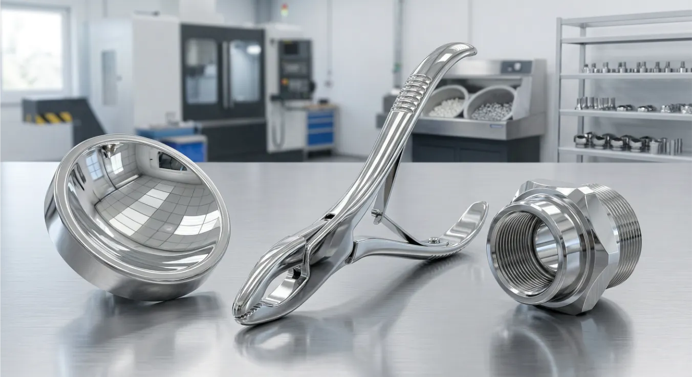
Progressive Abrasive Removal —
From Machined Surface to Mirror in Measured Steps
Polishing is a controlled, progressive sequence of abrasive steps — each stage removes the scratch pattern left by the previous step and replaces it with a finer one. Starting from the as-machined Ra (typically Ra 0.8–3.2 μm), each stage reduces the scratch depth and peak height until the target Ra is achieved.
The fundamental rule: you cannot skip grits. Jumping from 240-grit abrasive directly to polishing compound leaves 240-grit scratches that the compound cannot remove — you polish around them, not through them. Our polishing routes are engineered from the starting Ra and target Ra: the starting grit, number of intermediate steps, and final compound grade are specified on the route card before work begins.
Ra is a measured dimensional parameter (ISO 1302 / ISO 4287) — not a visual assessment. We measure Ra with a contact profilometer after polishing on every part with a drawing Ra callout. The measurement location, direction, and cut-off wavelength (λc) are specified at DFM. Results are recorded on the inspection report.
Right Method for Every Geometry —
Material and Ra Target
Progressive Hand Polishing
Applied by trained polishers using rotating felt bobs, flap wheels, abrasive fingers, and diamond lapping films. This method is essential for complex 3D profiles, free-form surfaces, and internal contours that machine polishing cannot access. The operator works through a documented grit sequence: P240 → P400 → P800 → P1200 → P2000 → 3 μm diamond compound → 1 μm compound → 0.25 μm diamond paste.
Each stage is inspected under raking light at 45° before proceeding to the next grit. A common operator error — applying too much pressure at the compound stage — produces local smearing and uneven reflectance. Our polishers use light, overlapping strokes with fresh compound on a clean felt bob at each step. Raking light at 45° reveals any remaining scratches from the previous stage before the part proceeds.
Electrolytic (Electrochemical) Polishing
The part is immersed in an acid electrolyte and DC current is applied — metal dissolves from the peaks of the surface faster than from the valleys (higher current density at peaks), smoothing the surface by electrochemical action without any mechanical contact. The result is an exceptionally uniform Ra across all surfaces the electrolyte contacts — including internal bores, recesses, and cross-holes that hand polishing cannot reach.
Electrolytic polishing simultaneously removes free iron contamination and enriches the chromium oxide passive layer on stainless steel — providing passivation equivalent to or better than ASTM A967 nitric acid passivation. For this reason it is the preferred final surface treatment for SS medical devices, food-processing equipment, and pharmaceutical vessel internals. No separate passivation step is required after electrolytic polishing.
Belt & Machine Polishing
Semi-automatic abrasive belt, wheel, and bobbing machine polishing for flat faces, cylindrical ODs, simple curves, and tube externals. Consistent belt speed and controlled contact pressure produce more uniform Ra than hand polishing on regular geometry — at significantly higher throughput. Used for flat aluminium panel pre-anodise finishing (Ra ≤ 0.4 μm before Type II anodise), stainless steel tube and bar finishing, and cylindrical component OD polishing before plating.
Belt polishing produces a directional scratch pattern — the grain runs in one consistent direction. This is often acceptable or desirable (producing the brushed satin appearance). For a non-directional polish, we switch to oscillating wheel polishing with compound. Belt polishing is typically 3–8× faster than hand polishing on regular geometry.
Lapping & Superfinishing
Ultra-precision abrasive processes for achieving Ra ≤ 0.1 μm and exceptional flatness (≤ 0.5 μm / 100 mm) simultaneously. Lapping uses a cast iron or ceramic surface plate with abrasive slurry — the part is moved in a randomising figure-8 pattern, averaging out any high spots to produce a mathematically flat surface. Used for valve seats, hydraulic sealing faces, and optical flats where Ra alone is insufficient — flatness deviation must also be controlled.
Superfinishing uses a reciprocating abrasive stone applied to rotating cylindrical surfaces (bearing races, shaft journals, crankshaft journals) under light pressure and cutting fluid. The process removes the surface amorphous layer left by grinding and creates a plateau-honed texture — peaks removed, valleys retained — that holds lubricant in service and dramatically reduces running-in wear in high-load bearings.
Polishing Specifications — What We Specify, Control, and Measure
Every parameter below is specified at DFM, applied during production, and verified at inspection.
| Parameter | Specification | How We Control It | Measurement |
|---|---|---|---|
| Surface Roughness Ra | Ra 0.05 – 0.8 μm Per drawing callout or application requirement | Engineered grit sequence on route card. Starting grit from machined Ra, diamond compound for Ra ≤ 0.2 μm. | Contact profilometer ISO 4287. Location and direction specified at DFM. |
| Material Removal | 0.005 – 0.05 mm per surface Electrolytic: 0.005–0.02 mm · Hand mirror: 0.03–0.05 mm | Stock allowance added at DFM. Precision bores dimensioned for post-polish nominal before machining. | CMM or micrometer pre/post-polish comparison on first-off. Documented for tight-tolerance features. |
| Grit Sequence | P240 → P400 → P800 → P1200 → P2000 → 3μm → 1μm → 0.25μm Adjusted to starting Ra and target Ra | Sequence on route card. Cannot be varied without engineering change. Inspector verifies compliance. | Route card sign-off. Visual raking-light check at each step before proceeding to next grit. |
| Surface Temperature | < 120 °C continuous · < 60 °C for hardened steel > HRC 55 Applies to all mechanical polishing methods | Intermittent polishing with cooling periods. Pyrometer monitoring for hardened mould steel. | Contact pyrometer on part surface. Documented for hardened parts where tempering is a risk (> 160 °C). |
| Electrolytic Parameters | 3–8 A/dm² · 3–12 min · 50–70 °C bath Stainless steel standard bath conditions | Temperature and current density monitored continuously. Time by timer. Electrolyte composition per SOP. | Pre/post Ra measurement. Visual uniformity check. Salt spray test on medical/food parts. |
| Masking Specification | All bores H8 and tighter · All threads · All sealing faces Specified at DFM on route card | Plugs, caps, wax, and tape rated for polishing compounds. Verified before polishing begins each batch. | Visual check of masked features before and after. CMM check of masked precision bores after polishing. |
Real Projects — Specification, Challenge, and Measured Result
Three production polishing jobs with actual Ra targets, materials, challenges, and profilometer-measured results.

Surgical Instrument Housing — Ra ≤ 0.2 μm + Passivation

Injection Mould Cavity — SPI A1 Mirror Finish, Ra ≤ 0.025 μm
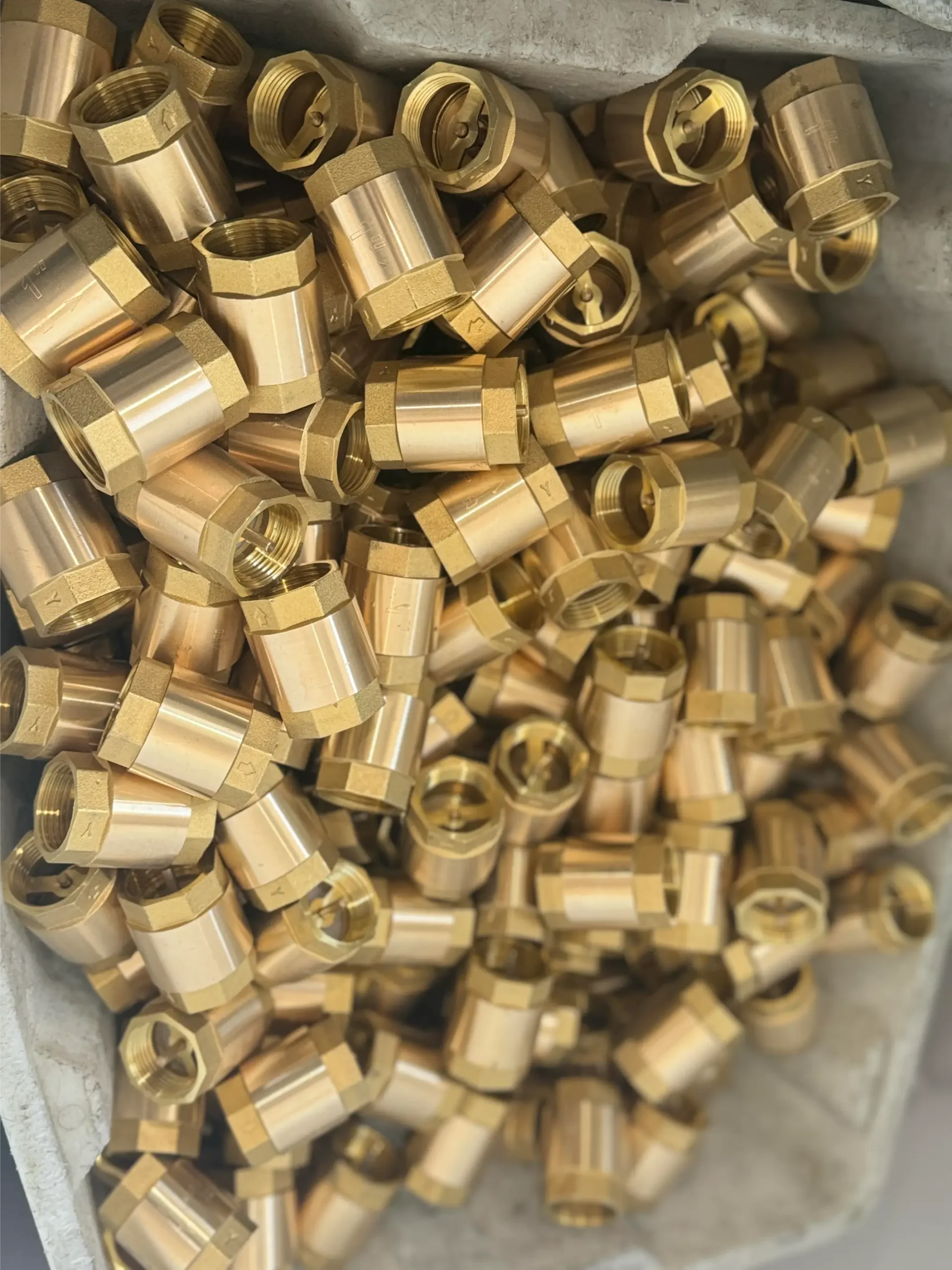
Hydraulic Valve Seating Face — Flatness ≤ 0.5 μm, 350 bar Service
Polishing by Material — Method, Ra, and Key Notes
Polishing — Detailed Technical Answers
Common technical questions about specifying polishing on CNC machined parts — with engineering-level answers.
O-ring face seal groove: Ra ≤ 0.8 μm — the O-ring deforms to fill minor irregularities. Over-polishing to Ra ≤ 0.05 μm adds cost with no functional benefit. Dynamic piston rod seal: Ra ≤ 0.2 μm — too smooth (Ra < 0.05 μm) prevents lubricant retention in the seal film and increases seal wear. Metal-to-metal valve seat: Ra ≤ 0.4 μm + flatness ≤ 1 μm. Hydraulic cylinder bore: Ra ≤ 0.4 μm plateau-honed.
Contact us with your seal type, fluid, and operating pressure — we will recommend the correct Ra rather than you having to over-specify.
Hand mirror polish (Ra 1.6 μm → Ra 0.05 μm): approximately 0.03–0.05 mm per surface. Fine hand polish (Ra 0.8 μm → Ra 0.2 μm): 0.01–0.02 mm. Electrolytic polish: 0.005–0.015 mm. Lapping: 0.001–0.005 mm.
For most external surfaces, this is within normal drawing tolerance — no pre-polish dimensional compensation needed. For tight-tolerance precision bores (H7/H6), sealing diameters, and thread pitch diameters: we calculate the pre-polish dimension at DFM so the post-polish dimension achieves the drawing nominal. Precision features that must not be polished are masked before polishing begins.
Passivation (ASTM A967 nitric or citric acid) dissolves free iron from the surface and restores the natural chromium oxide passive layer. It does not improve surface roughness and does not remove machining marks.
Electrolytic polishing smooths the surface (reduces Ra), removes more free iron than passivation, and produces a chromium-enriched passive layer 30–50× thicker than standard passivation. The chromium/iron ratio after electropolishing (Cr:Fe > 1.5) is significantly higher than after passivation alone — better corrosion resistance in salt spray testing. For medical and food-contact SS: electropolishing is the preferred single-step treatment — no separate passivation step is needed afterward.
Yes — method depends on bore geometry. Electrolytic polishing: reaches all internal surfaces the electrolyte contacts — including blind holes, cross-holes, and deep narrow bores. Most effective for internal SS surface improvement. Honing: polishes bore IDs with an expanding abrasive stone — achieves Ra ≤ 0.2 μm and corrects bore cylindricity simultaneously. Range ∅5–∅300 mm. Flexible abrasive tools: spiral-wound abrasive sheets — for short bores ∅8–∅50 mm needing Ra ≤ 0.4 μm. Very narrow deep bores (L/D > 10, diameter < 3 mm): electrolytic polishing is the only practical option.
Ra is measured with a contact profilometer (stylus type) per ISO 4287. Key measurement parameters: evaluation length (ln = 5 × cut-off λc — e.g., for Ra 0.05–0.4 μm: λc = 0.25 mm, ln = 1.25 mm). Stylus radius: 2 μm standard.
The inspection report shows: measured Ra value at each specified location, measurement direction, instrument ID and calibration date (traceable to NIST/NPL), and pass/fail against drawing tolerance. For first-article inspection of critical parts, we include the full surface profile trace as a PDF attachment.
Lapping is specified when both Ra and flatness must be controlled simultaneously — hand/belt polishing improves Ra but does not control flatness. Specify lapping when: flatness deviation must be ≤ 1 μm (polishing cannot achieve this consistently).
Typical lapping applications: hydraulic valve seating faces (metal-to-metal seal at high pressure), optical flats and windows (flatness ≤ λ/4), precision gauge faces (certified flatness for calibration traceability), ball valve seats (gas-tight shutoff). Our lapping plates range 100 mm to 400 mm diameter, accommodating parts up to 350 × 250 mm for flatness lapping.