info@hxcnc.com Shenzhen, China Reply within 24 hours
ISO 9001 : 2015 Get Instant Quote
Product Category
Scallop ≤0.003 · Ra 0.4 · G2 Cont. · ±0.01 Interface · MOQ 1
FSS / 001 — 010

G2 Constant-Scallop
Freeform Surface Shells

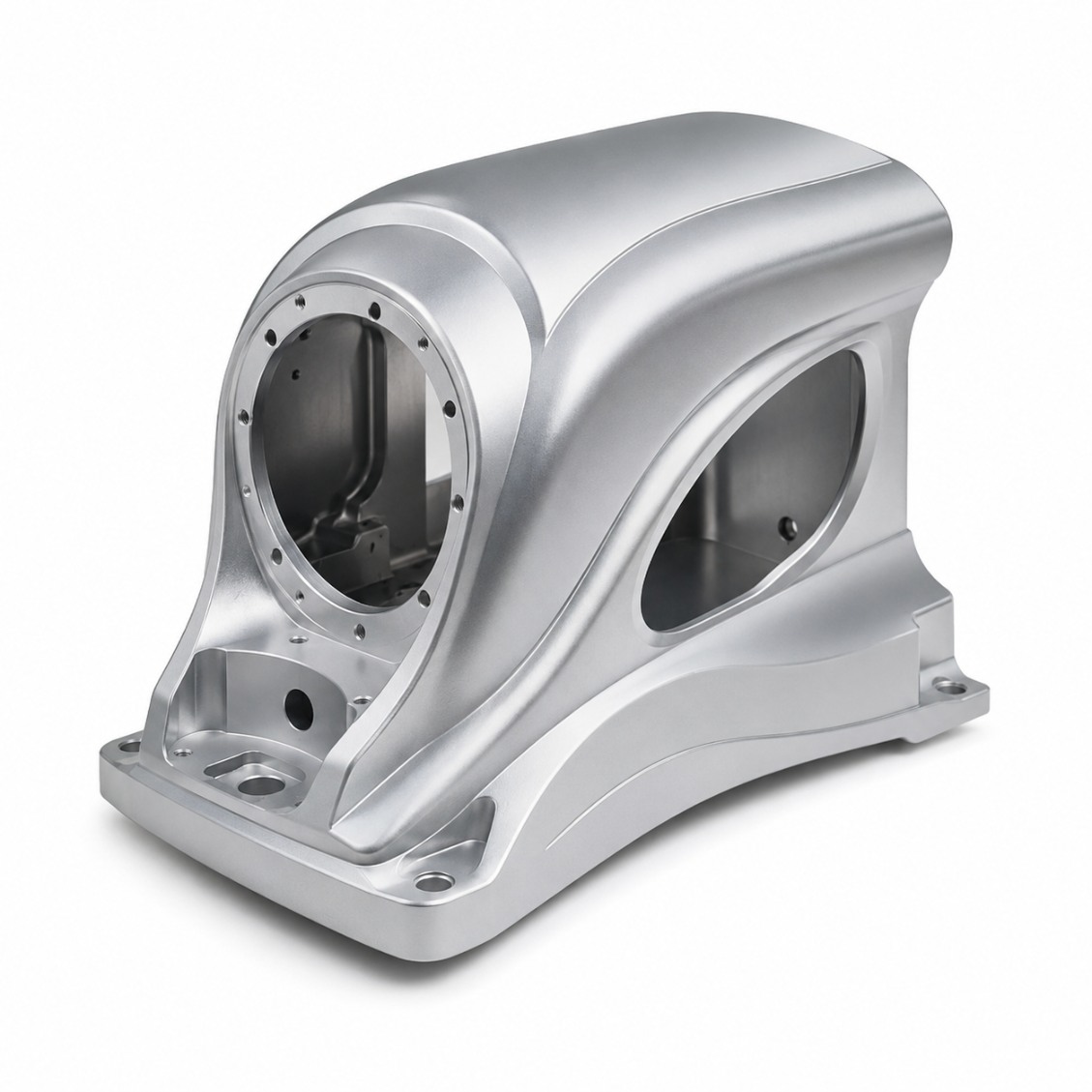
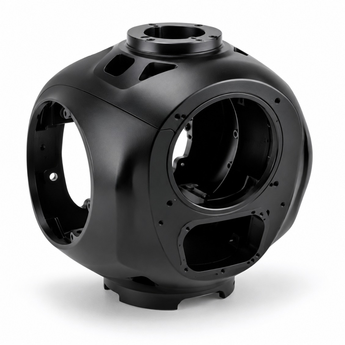
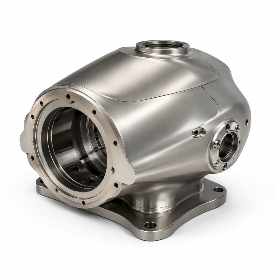
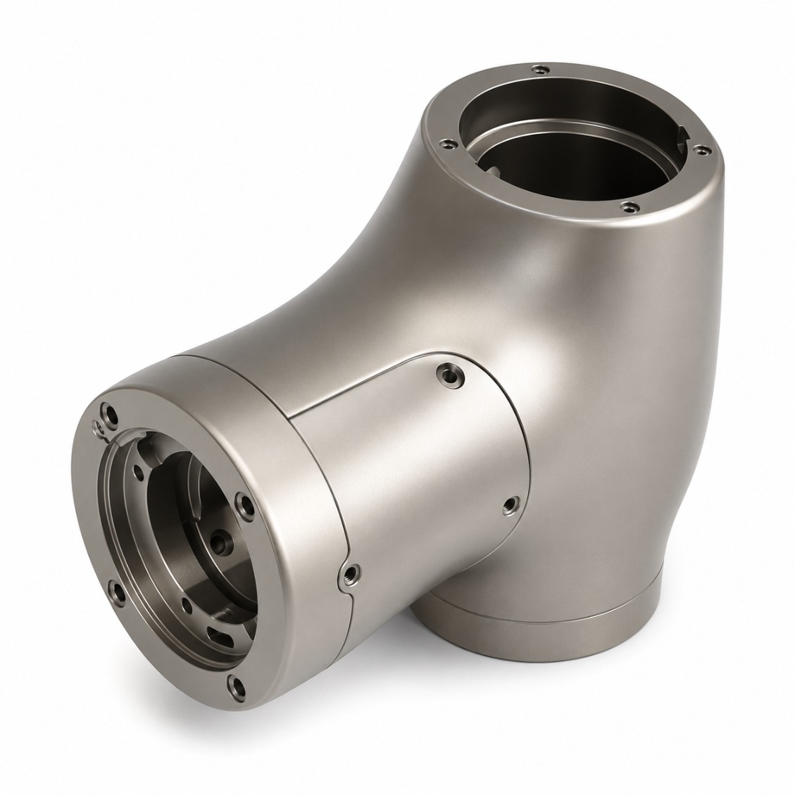
Custom 5-axis CNC machined freeform surface shells and enclosures — constant-scallop toolpaths with ≤ 0.003 mm theoretical scallop, visible surface Ra 0.4 µm direct from machine, G2 curvature continuity across all surface boundaries, assembly interface accuracy ±0.01 mm machined in the same setup. For robot housings, instrument enclosures, automation covers, and opto-mechanical structures.

Ra 0.4µm
Visible Surface
±0.01mm
Assembly Int.
G2
Continuity
PART DWG · FSS-001 ROBOT SHELL · Al 7075 HA · Ra 0.4 · G2 ISO 9001 · 5-AXIS · CMM + OPT SCAN
Constant Scallop
5-Axis Tilt 35°
FREEFORM SHELL · COMPOUND CURVE Al 7075 HA · CONST SCALLOP · Ra 0.4 · G2 ±0.01 INT BALL-NOSE 5-AX TILT SCALLOP ZOOM 50× ≤0.003 mm Ra 0.4 G2 FLANGE A FLANGE B SURFACE + INTERFACE · ONE SETUP SURFACE · CONTINUITY G0 positionfaceted G1 tangentvisible mark G2 curvature ◀invisible blend G3 accel.A-class show COSMETIC · TARGET Ra 0.4 → anodize ◀decorative Ra 0.8 → paintprimer ok Ra 1.6 → powderadhesion Mirror polishSUS Ra ≤0.1 SHELL · TYPE ROBOT ◀ UAV INSTR CONS UNDERCUT · 5-AX TILT MIN WALL 1.5 · COSMETIC MATERIAL · FINISH Al 7075 HA ◀Type III 15-25 µm Al 6061 Type IIdecorative ano SUS316L polishmedical · food Ti Grade 5 clearaerospace Bead-blast pre-fin.homogenise SCALE 1:1 · MM
Robot · UAV · Instrument · Medical · Consumer · Aero
Applications
Al 7075 HA · Al 6061 · SUS316L · Ti Gr5 · PEEK
Materials
48hr Quote · 7-Day Proto · MOQ 1
Service
Ra 0.4µm
Visible Surface Finish
all cosmetic faces
±0.01mm
Assembly Interface
accuracy
G2
Surface Continuity
no scallop marks
7 Days
Fastest Delivery
prototype orders
Why It's Difficult

Freeform Surface Shell Machining Challenges

A freeform shell must look perfect on the outside while fitting precisely on the inside — achieving both cosmetic surface quality and assembly interface accuracy simultaneously.

Surface Continuity (G2)
A cosmetic shell surface must be free of scallop marks, tool-lift defects, and surface waviness. HXC uses constant-scallop toolpaths with ≤ 0.003 mm theoretical scallop height on visible surfaces — producing Ra ≤ 0.4 µm direct from the machine.
🔩
Assembly Interface Accuracy
The shell must mate with internal components at flanges, bosses, and datum faces — to ±0.01 mm. All assembly interfaces are machined in the same 5-axis setup as the cosmetic surfaces, ensuring the external appearance and internal fit are referenced to the same coordinate system.
🎨
Pre-Finishing Preparation
Visible surfaces that will be anodized or painted must be machined without marks that would show through the finish. HXC selects tool direction and step-over to ensure surface marks are below the finishing process noise floor.
Our Work

Freeform Shells & Enclosures We've Made

Robot housings, instrument enclosures, and opto-mechanical structures — cosmetic finish, precision assembly interfaces.
Request Similar Part
Collaborative Robot Outer HousingAl 7075 · Robot
Collaborative Robot Outer Housing
Ra 0.4µm · HA · 30 pcs
Precision Instrument EnclosureAl 6061 · Instrument
Precision Instrument Enclosure
Complex curve · Ano · 20 pcs
UAV Payload ShellAl 7075 · UAV
UAV Payload Shell — Freeform
Lightweight · Ano black · 50 pcs
Medical Device Freeform ShellSUS316L · Medical
Medical Device Freeform Shell
Passivated · Ra 0.4µm · 15 pcs
Camera Module Freeform BodyAl 7075 · Camera
Camera Module Freeform Body
G2 surface · Anodized · 40 pcs
Aerospace Sensor HousingTi Grade 5 · Aero
Aerospace Sensor Housing
Ti · Ra 0.4µm · 8 pcs
Opto-Mechanical HousingAl 7075 · Optical
Opto-Mechanical Housing
Curved · No facets · 12 pcs
Consumer Device Structural ShellAl 7075 · Consumer
Consumer Device Structural Shell
Complex profile · 100 pcs
Capabilities & Tolerances

What We Can Deliver

Typical specifications — confirm exact requirements at enquiry.

Min surface scallop0.003 mm theoretical
Visible surface finishRa 0.4 µm standard
Assembly interface tol.±0.01 mm
Surface continuityG2 (curvature-continuous)
Undercut handling5-axis tilt access
Min wall (cosmetic)1.5 mm
MaterialsAl, SS, Ti, PEEK
Machining5-axis simultaneous
FinishingAnodize, bead blast, paint-ready
InspectionCMM + optical surface scan
Lead time (proto)7–10 days
Lead time (batch)12–18 days
How It Works

From Drawing to Finished Part

Upload your 2D/3D file — DFM feedback, toolpath planning, and confirmed lead time within 48 hours.

01
Upload Drawing
STEP, IGES, DXF or PDF. Include surface quality and tolerance callouts.
02
DFM & Toolpath
Free DFM — undercuts, thin walls, surface strategy.
03
5-Axis & QC
5-axis CNC, in-process probing, CMM + optical surface scan.
04
Ship Worldwide
Full dimensional report enclosed. DHL / FedEx / sea freight.
Reviews

Trusted by Engineers Worldwide

★★★★★
"The cosmetic surface quality on our robot housings was exceptional — anodize laid down evenly with no visible toolmarks. Every part passed our incoming inspection."
AK
Alex K.
Industrial Designer · Germany
★★★★★
"HXC understood the 5-axis toolpath challenges immediately. Their DFM feedback caught an undercut issue we had missed. Lead time as quoted."
SL
Sophie L.
Design Engineer · France
★★★★★
"We've run three production batches of complex curved parts through HXC. Dimensional consistency batch-to-batch is the best we've seen from any supplier."
JT
James T.
Senior Procurement Manager · UK
FAQ

Freeform Surface Shells — FAQ

Engineering and procurement questions answered by our 5-axis machining team.

Yes — HXC machines cosmetic freeform surfaces using constant-scallop 5-axis finishing toolpaths. The stepover is calculated to achieve a theoretical scallop height ≤ 0.003 mm, resulting in Ra ≤ 0.4 µm directly from the machine without manual polishing. Batch-to-batch consistency is controlled by using the same NC programme and verified by optical surface scan on the first article of each batch.
Multi-surface transitions (where two freeform surfaces meet): (1) G2 continuity toolpaths are programmed at all surface boundaries — the tool maintains curvature continuity across the boundary, not just tangency; (2) Boundary blend passes are added where needed to smooth the transition zone; (3) Optical surface scan of the finished part identifies any transition discontinuities before the part is approved for delivery.
Yes — visible surfaces intended for anodizing are machined to Ra ≤ 0.4 µm with scallop marks oriented uniformly (parallel to the long axis of the part). This ensures the anodize layer produces a uniform, consistent appearance. For parts requiring bead-blast before anodize, we machine to Ra 0.8 µm and the bead blast homogenises the texture. For paint or powder coat: Ra 0.8–1.6 µm provides good adhesion.
Undercuts are accessed by 5-axis tilt — the tool tilts to reach the undercut area without a separate setup. For severe undercuts (>45° beyond vertical), we use tilted vise or rotary fixture positioning and machine the undercut region from a second tilt angle in the same programme. Deep undercuts that cannot be accessed by 5-axis tilt are reviewed during DFM — we advise on split-line options or alternative clamping strategies.
Al 7075-T6: best balance of machinability, surface quality after anodizing, and structural strength. Al 6061-T6: slightly better anodize cosmetic result than 7075, lower strength. SUS316L mirror polished: for medical and food-contact shells requiring a reflective finish. Ti Grade 5: for aerospace and weight-critical shells — note Ti does not anodize to a coloured decorative finish; clear anodize only.
Type II anodize: 5–8 µm — standard decorative and corrosion protection. Typical for robot housings and instrument enclosures. Type III hard anodize: 15–25 µm — for shells requiring wear resistance (e.g., UAV housings exposed to abrasion). Dimensional pre-compensation applied before anodize on precision assembly interfaces.
Yes — HXC can accept customer-supplied 3D scan data (point cloud or mesh) as the machining reference. The scan is converted to a parametric surface model for CAM programming. This approach is used for: (1) replicating legacy parts where no CAD exists; (2) reverse-engineering competitor products; (3) producing matched housings for an existing assembly.
Prototype (freeform shell, new CAM programme): 7–10 days. Small batch (10–50 pcs): 10–16 days. Production with anodizing: 14–20 days. Mirror-polish SUS316L shells: add 3–5 days.
Get a Quote

Send Your Drawing.
Get a Quote.

Every enquiry includes a DFM review — tolerance feasibility, material confirmation, and process approach confirmed before production starts. MOQ 1 piece.

24hr
Quote Response
MOQ 1
Prototypes OK
ISO
9001:2015
📐
DFM Review on Every Enquiry
Tolerance feasibility, fixturing strategy, and material confirmation. Specific, actionable feedback — not generic pushback.
🎯
First Article Inspection — Standard
FAI report on every new run. Material certs and surface treatment certs included with every shipment.
🔄
Same Process: Prototype to Production
Process plan from your prototype applies to production batches. No re-qualification when you scale.
3 / 4 / 5-Axis CNC + Turning
Complex structural parts, shafts, housings, and transmission components. Metals and engineering plastics.
ISO 9001:2015 3/4/5-Axis Milling CNC Turning CMM Inspection Global Delivery