
Product Category
Wall ≥1.0mm · Runout ≤0.005mm · Ra 0.4µm · Chatter-Free CNC
TWS / 001 — 008
Distortion-Free
Thin-Wall Shafts
Precision CNC machined thin-wall shafts with wall thickness down to 1.0 mm. Dedicated expanding-mandrel fixturing and sequential light cutting eliminate chatter and clamping distortion. OD runout ≤ 0.005 mm, Ra 0.4 µm ground — for lightweight drives, encoders, and medical instruments.
≥1.0mm
Min Wall
≤0.005mm
OD Runout
Ra 0.4µm
Ground OD
PART DWG · TWS-000 ENCODER SHAFT · SUS316L · WALL 2mm
ISO 9001 · EXPANDING-MANDREL GROUND
Wall t = 2.0 mm
↗ Runout ≤ 0.005
Encoder · Endoscope · Aero · Robot · Optical · Pump
Use Cases
SUS316L · Al 6061/7075 · Ti Gr5 · PEEK · SUS303
Materials
48hr Quote · 5-Day Proto
Service
≥1.0mm
Min Wall Thickness
specialist fixturing
specialist fixturing
≤0.005mm
OD Runout
after grinding
after grinding
Ra 0.4µm
Ground OD Finish
bearing-seat standard
bearing-seat standard
5 Days
Fastest Delivery
prototype orders
prototype orders
Our Work
Request Similar Part →
Thin-Wall Shafts We Have Made
Precision CNC machined thin-wall shafts for automotive, robotics, aerospace, medical, and industrial applications.
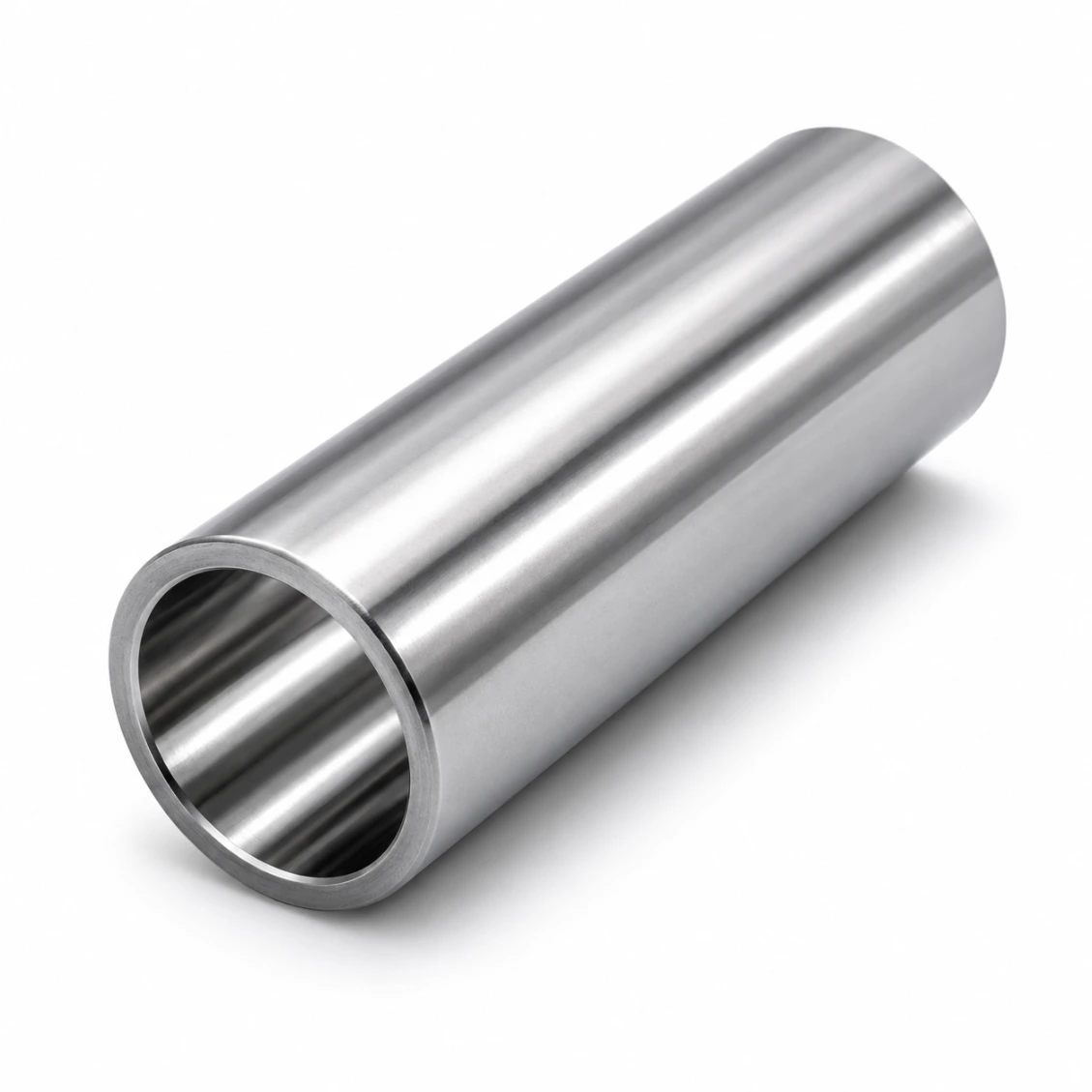 Al 6061 · Encoder
Thin-Wall Encoder Shaft
OD Ø20/ID Ø16mm · Wall 2mm · 200 pcs
 SUS316L · Medical
Thin-Wall Medical Shaft — Endoscope
OD Ø8/ID Ø5.5mm · Wall 1.25mm · 50 pcs
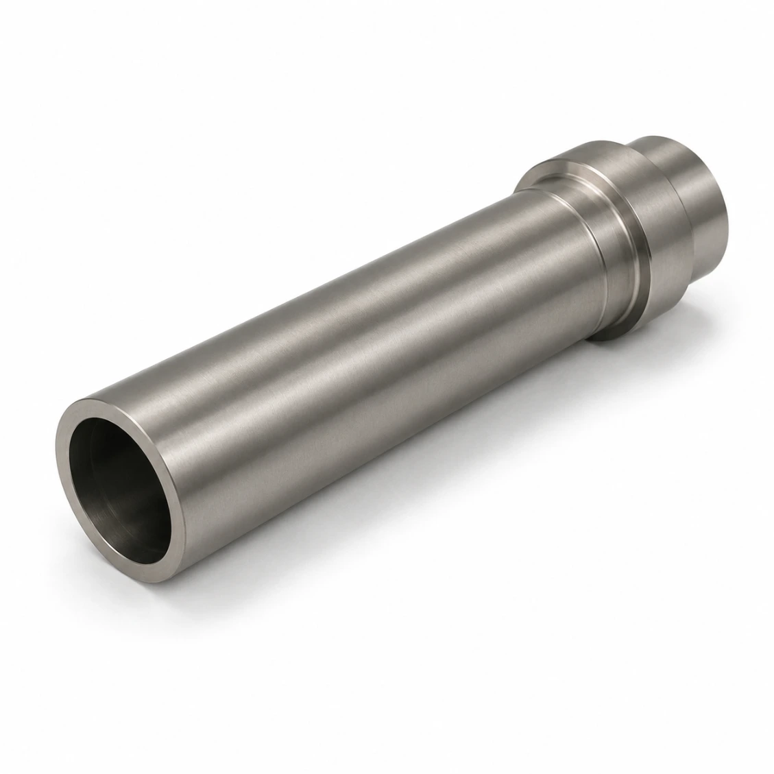 Ti Grade 5 · Aero
Thin-Wall Actuator Shaft — Aero
OD Ø18/ID Ø14mm · Wall 2mm · 20 pcs
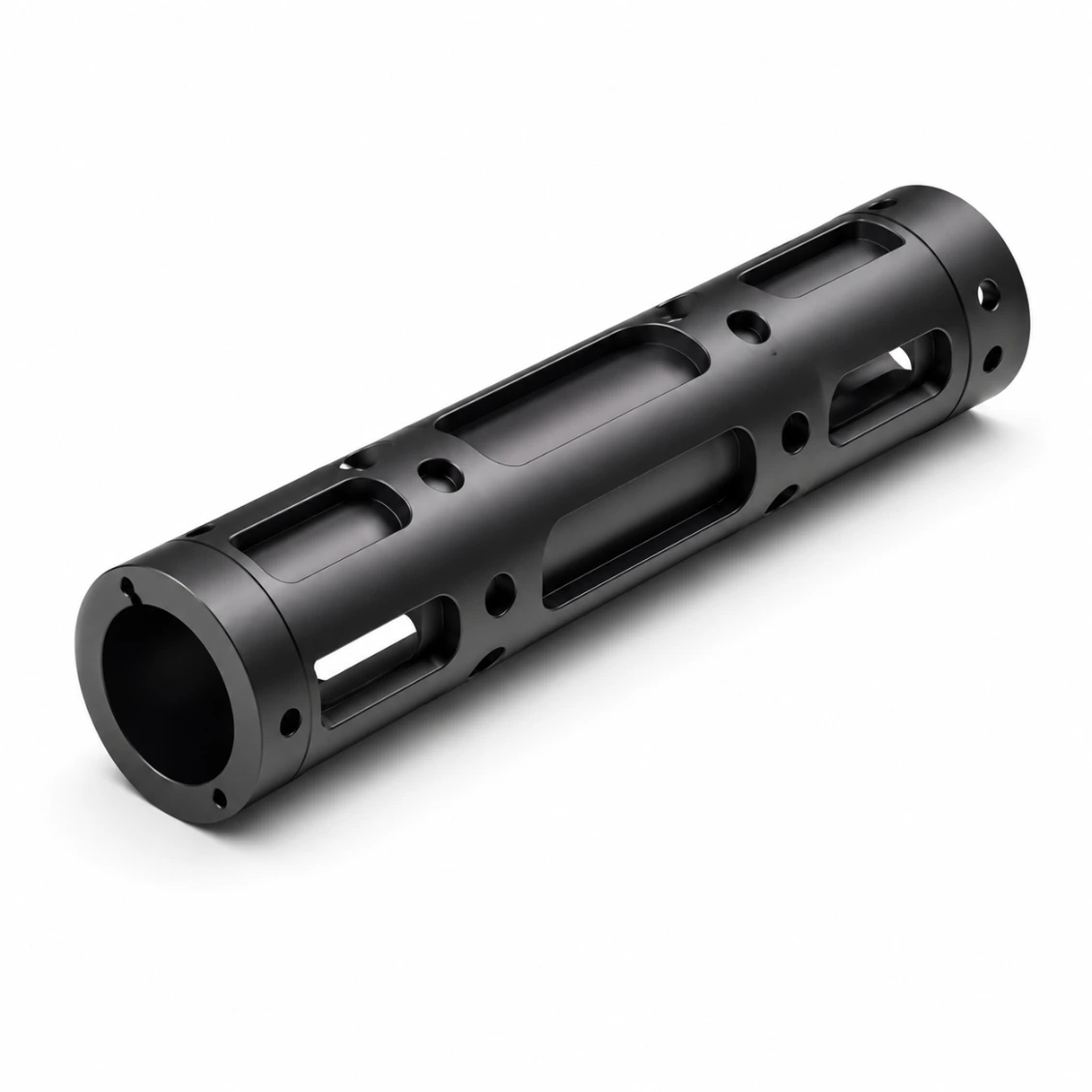 Al 7075 · Robot
Thin-Wall Rotor Shaft — Robot
OD Ø25/ID Ø21mm · Anodized · 60 pcs
C45 · Instrument
Thin-Wall Optical Shaft
OD Ø14/ID Ø11mm · Ra 0.2µm · 80 pcs
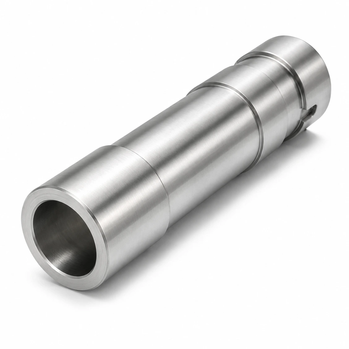 SUS303 · Pump
Thin-Wall Pump Shaft
OD Ø30/ID Ø24mm · Passivated · 120 pcs
 PEEK · Sterilisable
Thin-Wall PEEK Shaft — Surgical
OD Ø12/ID Ø9mm · Wall 1.5mm · 30 pcs
 CMM Verified
Wall Thickness & Runout Verified
Every piece CMM + ultrasonic wall check
How It Works
From Drawing to Finished Part
Upload your drawing — material, tolerances, and surface treatment. Quote in 48 hours.
01
Upload Drawing
STEP, DXF, PDF, or sketch with key dimensions and tolerances.
02
Quote in 48h
Material, process, surface treatment, and firm lead time.
03
CNC Machine & Inspect
Precision turning, grinding, CMM verification, surface treatment.
04
Ship Worldwide
Full dimensional report. DHL / FedEx / sea freight.
Reviews
Trusted Thin-Wall Shafts Manufacturer
★★★★★
"Excellent dimensional consistency across every batch. CMM report matched our incoming inspection perfectly. Lead time as promised."
AK
Alex K.
Mechanical Engineer · Germany
★★★★★
"HXC's DFM review caught two design issues before production. Finished parts were perfect first time. Strongly recommended."
SL
Sophie L.
Design Engineer · France
★★★★★
"Three years sourcing precision shafts from HXC. Quality consistent, lead times reliable, engineers always responsive."
JT
James T.
Senior Engineer · UK
FAQ
Thin-Wall Shafts — Frequently Asked Questions
Technical and sourcing questions answered by our engineers.
A thin-wall shaft is a hollow shaft where the ratio of wall thickness to OD is very small — typically wall/OD < 0.15. At this ratio, the shaft is prone to chatter vibration during turning, radial distortion under clamping pressure, and thermal distortion during heat treatment. Successful thin-wall shaft machining requires specialised fixtures (expanding mandrels or soft jaws), sequential light cuts, and careful heat treatment selection (nitriding over carburizing to minimise distortion).
In steel and stainless: 1.0 mm minimum wall for diameters above Ø10 mm. In aluminium: 1.5 mm minimum. In titanium: 1.2 mm minimum. In PEEK and engineering plastics: 1.0 mm. Below these limits, clamping forces during OD turning distort the bore, and the finished part springs back when unclamped, causing non-roundness. For walls thinner than 1.0 mm, consider electroforming or tube stock as the blank rather than machining from solid.
HXC uses three fixturing methods for thin-wall shaft machining: (1) Expanding mandrel — a hydraulic or mechanical mandrel expands to grip the bore ID uniformly, distributing clamping force without local deformation. (2) Soft jaws bore-matched to the part OD — maximises contact area to reduce unit pressure. (3) Steady rests for long thin-wall shafts — supports the workpiece midspan to prevent deflection and chatter. Method selection depends on shaft OD/length ratio and material.
Gas nitriding is the preferred hardening method for thin-wall shafts: it operates at 520°C (vs 900°C for carburizing), has no quench step, and produces very low distortion — case depth 0.1–0.3 mm, surface hardness HV 700–1,000. Induction hardening is acceptable for thicker walls (wall ≥ 3 mm) if the induction coil can be controlled to avoid through-heating. Carburizing and quenching are generally avoided for thin-wall shafts due to high distortion risk.
Prototype (1–5 pcs, turned + ground): 5–8 days. Small batch (10–50 pcs): 8–14 days. Production (100–1,000 pcs): 12–18 days. Stainless or titanium: add 2–4 days. Rush production available.
SUS316L / SUS303 stainless for food, pharma, marine, medical. Al 6061 / Al 7075 hard-anodized for lightweight and encoder bodies. Ti Grade 5 for aerospace and biocompatible medical. 42CrMo4 nitrided for industrial drives. PEEK / POM for sterilizable or self-lubricating applications. Tube stock blank available to minimise material removal on very thin walls.
HXC measures wall thickness using a calibrated ultrasonic wall thickness gauge at multiple angular positions and axial stations. For critical thin-wall shafts, CMM measurement of bore diameter and OD diameter at the same axial position gives an independent wall thickness calculation. Both measurements are reported on the inspection certificate.
Yes — aluminium thin-wall shafts are regularly hard-anodized. However, the anodizing process adds 15–35 µm to each surface, which means the bore grows and the OD shrinks slightly (anodizing replaces aluminium rather than coating over it). For tight-tolerance thin-wall shafts, the pre-anodize bore and OD are machined to compensate for the coat build-up — HXC calculates the pre-anodize allowance and machines accordingly.