info@hxcnc.com Shenzhen, China Reply within 24 hours
ISO 9001 : 2015 Get Instant Quote
Product Category
Angle ±0.05° · Face ≤0.01 · 5-Axis · CMM Verified · MOQ 1
CAB / 001 — 010

5-Axis Compound-Angle
Complex-Angle Brackets

Non-standard angle brackets precision machined from solid — angular tolerance ±0.05°, contact face flatness ≤ 0.01 mm, any alloy. For robot supports, equipment mounts, optical platforms, and aerospace fixture brackets where standard bent sheet metal cannot meet the specification. All faces in a single 5-axis setup, no angular error accumulation.

±0.05°
Angular Tol.
≤0.01mm
Face Flatness
5-Axis
Single Setup
PART DWG · CAB-001 COMPOUND BRACKET · Al 7075 HA · 35°+7° · ±0.05° ISO 9001 · 5-AXIS · CMM
35° Primary Tilt
±0.05° CMM
COMPOUND-ANGLE BRACKET · ISO VIEW Al 7075-T6 HA · 90×60×40 · 35°+7° · ±0.05° ±0.05° CONTACT FACE Ra 0.8 · ≤0.01 FLAT 35° +7° TWIST A SIDE · COMPOUND PROFILE 35° SINGLE-SETUP 5-AXIS ANGULAR · TOL. Bent sheet metal±0.5° 5-axis CNC ◀±0.05° Precision-grade±0.02° Interferometricspec / lap COMPOUND · ANGLE Single tilt15° / 30° / 45° Compound ◀15° + 7° Multi-face3+ angled Custom geometryDFM review BRACKET · FORM CANTI STRUT CPND ◀ MULTI ALL CONTACT FACES SINGLE SETUP · NO STACKING MATERIAL · TREATMENT Al 7075-T6 HA ◀robot / UAV / light 42CrMo4 hardenedheavy equip SUS304 / 316Lcorrosion Ti Grade 5aerospace / weight C45 black oxideindustrial std SCALE 1:1 · MM
Robotics · Aerospace · Industrial · Medical · Optical
Applications
Al 7075 HA · 42CrMo4 · SUS316L · Ti Gr5
Materials
48hr Quote · 6-Day Proto · MOQ 1
Service
±0.05°
Angular Tolerance
between mating faces
≤0.01mm
Contact Face Flatness
assembly surface grade
5-Axis
Complex Geometry
single setup machining
6 Days
Fastest Delivery
prototype orders
Why It's Difficult

Complex-Angle Bracket Challenges

Non-standard angles cannot be produced by bending or standard milling. Every functional face must be machined and verified to ensure the bracket transmits load in the correct direction.

Angle Accuracy
Standard bent sheet metal holds ±0.5° at best. Our 5-axis machined brackets hold ±0.05° — critical for robot support members and optical alignment brackets.
Load Path Integrity
Each face carries a different load vector. Our engineers review the force diagram to ensure wall thickness, fillet radii, and face orientation are optimised before cutting.
🔩
Interface Compatibility
Mating faces must be flat and in the correct angular relationship for bolted joints to clamp without distortion. We machine all contact faces in a single setup for guaranteed relationship.
Our Work

Complex-Angle Brackets We've Made

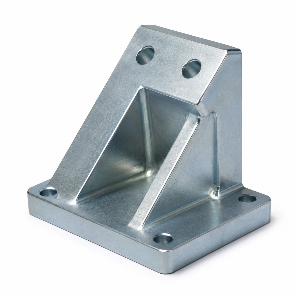
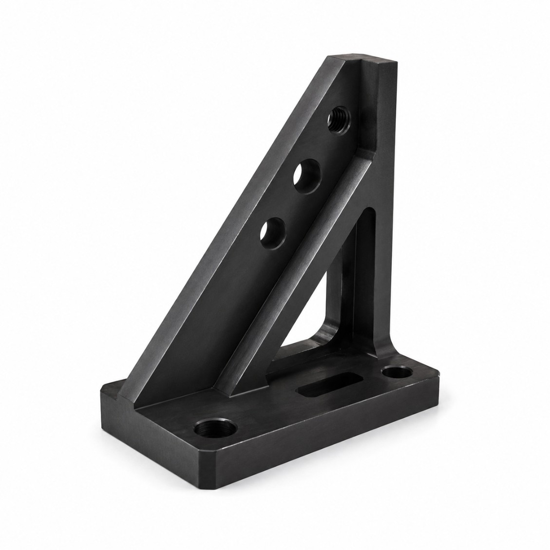
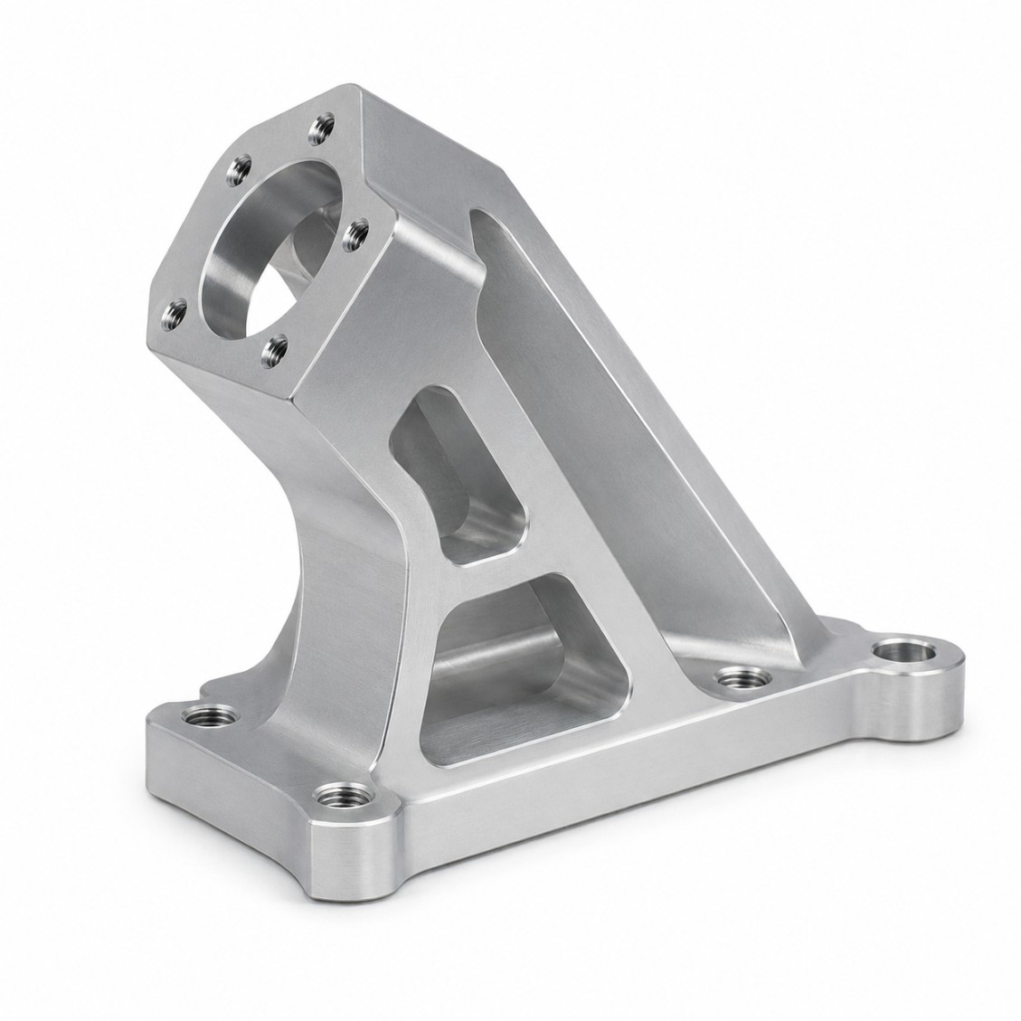
Custom angle brackets for robots, equipment, and aerospace — every contact face CMM-verified.
Request Similar Part
Robot Support Bracket 35°Al 7075 · Robot
Robot Support Bracket — 35°
5-axis · Anodized · 80 pcs
Equipment Diagonal Brace42CrMo4 · Equip.
Equipment Diagonal Brace
HRC 48 · Zn plated · 200 pcs
Aerospace Fixture BracketAl 6061 · Aero
Aerospace Fixture Bracket
±0.03° · Hard ano · 10 pcs
Vision Module Tilt BracketSUS304 · Vision
Vision Module Tilt Bracket
15° · CMM verified · 50 pcs
UAV Antenna MountTi Gr5 · UAV
UAV Antenna Mount
20° compound · 25 pcs
Optical Platform BracketAl 7075 · Optical
Optical Platform Bracket
30° · Ra 0.8µm · 30 pcs
Industrial Diagonal SupportC45 · Industrial
Industrial Diagonal Support
45° · Black oxide · 300 pcs
Medical Arm Angle BracketSUS316L · Med.
Medical Arm Angle Bracket
Compound · Passivated · 15 pcs
How It Works

From Drawing to Finished Part

Upload your 2D/3D file — receive DFM feedback, quote, and confirmed lead time within 48 hours.

01
Upload Drawing
STEP, DXF, PDF or sketch. 2D + 3D preferred.
02
DFM & Quote
Free DFM feedback + material, lead time, cost — in 48 h.
03
5-Axis CNC & QC
5-axis CNC, CMM inspection, full dimensional report.
04
Ship Worldwide
DHL / FedEx / sea freight. Inspection report enclosed.
Reviews

Trusted by Engineers Worldwide

★★★★★
"The CMM report matched our incoming inspection perfectly. Every critical dimension was within spec on the first article. Lead time exactly as quoted."
AK
Alex K.
Mechanical Engineer · Germany
★★★★★
"HXC's DFM review caught a tolerance stack issue before we committed to production. The finished parts were perfect and batch consistency was excellent."
SL
Sophie L.
Design Engineer · France
★★★★★
"We've sourced over 30 part numbers from HXC across three years. Quality is consistent, lead times are reliable, and the engineering team is always responsive."
JT
James T.
Senior Buyer · UK
FAQ

Complex-Angle Bracket — FAQ

Common questions from engineers and procurement teams — answered by our manufacturing team.

Bent sheet metal holds angular tolerance of ±0.5°–1° and has rough contact faces. For robot support structures, sensor mounts, and optical alignment brackets where contact face angles must be accurate to ±0.05° and surfaces must be flat to ≤ 0.01 mm, only 5-axis CNC machining from solid can reliably achieve the specification.
Standard: ±0.05° between any two contact faces, measured by CMM. For precision optical or interferometric brackets: ±0.02° achievable with additional process steps. Compound angles (e.g., 15.5° tilt + 7° twist) are machined in a single 5-axis setup — no angular error accumulation from multiple setups.
Al 7075-T6 (hard anodized): most common for robotics and UAV. 42CrMo4: high-load equipment supports. SUS304/316L: corrosion-resistant environments. Ti Grade 5: aerospace and weight-critical applications.
All contact faces are measured on our Zeiss CMM with flatness reported in µm. For bolted joint faces, flatness ≤ 0.01 mm is standard. The dimensional report with flatness, angularity, and hole-position data is included with every order.
Yes — 5-axis machining handles any combination of angular features. The bracket is fixtured once; all faces are machined in that single setup, ensuring every angular relationship is held to the same coordinate system. This eliminates the angular error that would accumulate from sequential setups on a 3-axis machine.
Al 7075-T6 hard anodized gives the best stiffness-to-weight ratio for machined angle brackets. Where weight is critical (UAV, aerospace), HXC also offers topology-informed pocket milling — removing material from non-load-bearing zones while maintaining angular interface accuracy.
Prototype (1–3 pcs): 6–9 days. Small batch: 9–14 days. Production: 14–20 days. Compound angle parts with multiple precision contact faces: add 1–2 days for CMM verification steps.
Yes. Upload your STEP or DXF file and our engineers will review: force path alignment, minimum wall thickness at angle intersections, fillet radius for fatigue life, and fixturing strategy. Free DFM review is included with every quotation.
Get a Quote

Send Your Drawing.
Get a Quote.

Every enquiry includes a DFM review — tolerance feasibility, material confirmation, and process approach confirmed before production starts. MOQ 1 piece.

24hr
Quote Response
MOQ 1
Prototypes OK
ISO
9001:2015
📐
DFM Review on Every Enquiry
Tolerance feasibility, fixturing strategy, and material confirmation. Specific, actionable feedback — not generic pushback.
🎯
First Article Inspection — Standard
FAI report on every new run. Material certs and surface treatment certs included with every shipment.
🔄
Same Process: Prototype to Production
Process plan from your prototype applies to production batches. No re-qualification when you scale.
3 / 4 / 5-Axis CNC + Turning
Complex structural parts, shafts, housings, and transmission components. Metals and engineering plastics.
ISO 9001:2015 3/4/5-Axis Milling CNC Turning CMM Inspection Global Delivery