≥1.5 Wall · Deep Cavity · ±0.015 Interface · 5-Axis
CSF / 001 — 010
Internal-Datum 5-Axis Cavity Support Frames
Precision 5-axis machined cavity support frames — deep-cavity access to internal mounting bosses, multiple assembly interfaces, wall thickness ≥ 1.5 mm. Internal features positioned to ±0.015 mm relative to external assembly datums — no datum-transfer error. For equipment enclosures, instrument chassis, control modules, and robot internal structures.
PART DWG · CSF-000 INSTRUMENT FRAME · Al 7075-T6 · DEEP CAVITY · 6 BOSSESISO 9001 · 5-AXIS · CMM
Int Bosses → Ext Datum
L/D 8:1 Long-Reach
Instrument · Robotics · Aerospace · Medical · Optical
Applications
Al 7075 · Al 6061 · SUS316L · Ti Gr5 · PEEK
Materials
48hr Quote · 8-Day Proto
Service
≥1.5mm
Minimum Wall cavity support frame
Deep Cavity
Internal Access 5-axis machining
±0.015mm
Interface Accuracy all mounting faces
8 Days
Fastest Delivery prototype orders
Why It's Difficult
Cavity Frame Machining Challenges
Machining inside a cavity requires long-reach tooling, careful vibration management, and 5-axis access planning. Internal mounting features must be positionally accurate relative to external assembly datums.
🏗️
Deep Cavity Access
Internal bosses, mounting pads, and cable-routing features deep inside the cavity require long-reach tooling with vibration-damping toolholders and optimised chip evacuation strategies.
🔩
Internal Interface Accuracy
Mounting features inside the cavity must be positioned accurately relative to the external assembly face. 5-axis machining maintains this relationship in a single setup — avoiding datum-transfer errors.
📐
Structural Rigidity
The frame must provide structural support to the internal components it carries. Rib placement, wall thickness at load points, and boss geometry are reviewed in DFM to balance weight and stiffness.
Our Work
Cavity Support Frames We've Made
Equipment enclosures, instrument chassis, and robot internal frames — deep cavity machining verified.
"The internal mounting bosses on every part matched our assembly fixture exactly. Articulated CMM report verified every internal feature in the external coordinate system."
AK
Alex K.
Mechanical Engineer · Germany
★★★★★
"HXC's DFM review identified a long-reach tool feasibility issue early and suggested a split-cavity design — saved us a costly redesign downstream."
SL
Sophie L.
Design Engineer · France
★★★★★
"Three years sourcing instrument chassis from HXC. Quality consistent, batch-to-batch dimensional consistency excellent, engineering team always responsive."
JT
James T.
Senior Buyer · UK
FAQ
Cavity Support Frames — FAQ
Common questions answered by our manufacturing team.
A cavity support frame is a structural component where the functional mounting interfaces are located inside an enclosed or semi-enclosed cavity. The frame carries internal components (PCBs, sensors, optics) on bosses and pads machined into the cavity walls — providing structural support and precise positioning simultaneously.
Using extended-reach tooling (L/D up to 8:1) with vibration-damping toolholders: cavity depth up to 300 mm with ±0.02 mm positional accuracy on internal features. For deeper cavities, we use 5-axis table tilting to access features from multiple angles without reaching the L/D limit.
Internal features are measured using our CMM with articulated scanning probe — the probe head rotates to access internal faces and bosses. All internal dimensions are reported in the same coordinate system as the external assembly interfaces, confirming their relative positions.
Yes — anodizing penetrates the entire surface including internal cavity surfaces and blind pockets, provided the electrolyte can drain fully. For complex cavities with blind features, we drill drain/vent holes at the lowest points before anodizing, then plug them after processing if required.
Al 6061/7075: standard — excellent deep-cavity machinability, anodizable. SUS304/316L: medical, food, and corrosion-sensitive environments. PEEK: cleanroom, high-temperature sterilisable, or chemically aggressive environments. Ti Grade 5: aerospace where weight saving in the frame structure is critical.
HXC's engineers review the load inputs (component weight, vibration, shock) and design: rib placement at load-path intersections; gusset features at high-stress corners; minimum wall thickness at structural panels; and boss diameter at mounting interfaces. Material and wall recommendations are included in the free DFM review.
Yes — HXC machines O-ring grooves, thread inserts, and cover-mating faces to enable IP-rated sealing. The sealing face flatness and O-ring groove dimensions are verified by CMM. Pressure testing is available as an optional service for hydraulic or pneumatic cavity frames.
Every enquiry includes a DFM review — tolerance feasibility, material confirmation, and process approach confirmed before production starts. MOQ 1 piece.
24hr
Quote Response
MOQ 1
Prototypes OK
ISO
9001:2015
📐
DFM Review on Every Enquiry
Tolerance feasibility, fixturing strategy, and material confirmation. Specific, actionable feedback — not generic pushback.
🎯
First Article Inspection — Standard
FAI report on every new run. Material certs and surface treatment certs included with every shipment.
🔄
Same Process: Prototype to Production
Process plan from your prototype applies to production batches. No re-qualification when you scale.
⚙
3 / 4 / 5-Axis CNC + Turning
Complex structural parts, shafts, housings, and transmission components. Metals and engineering plastics.
ISO 9001:20153/4/5-Axis MillingCNC TurningCMM InspectionGlobal Delivery

 Al 7075 · Instrument
 Al 6061 · Equipment
 SUS304 · Medical
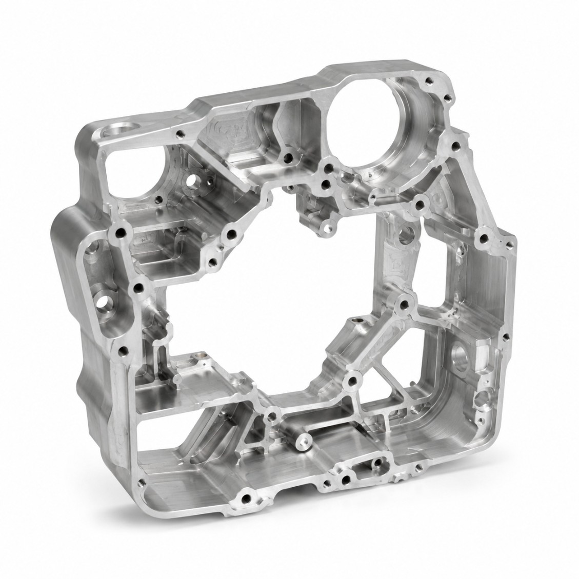 Al 7075 · Robot
 42CrMo4 · Industrial
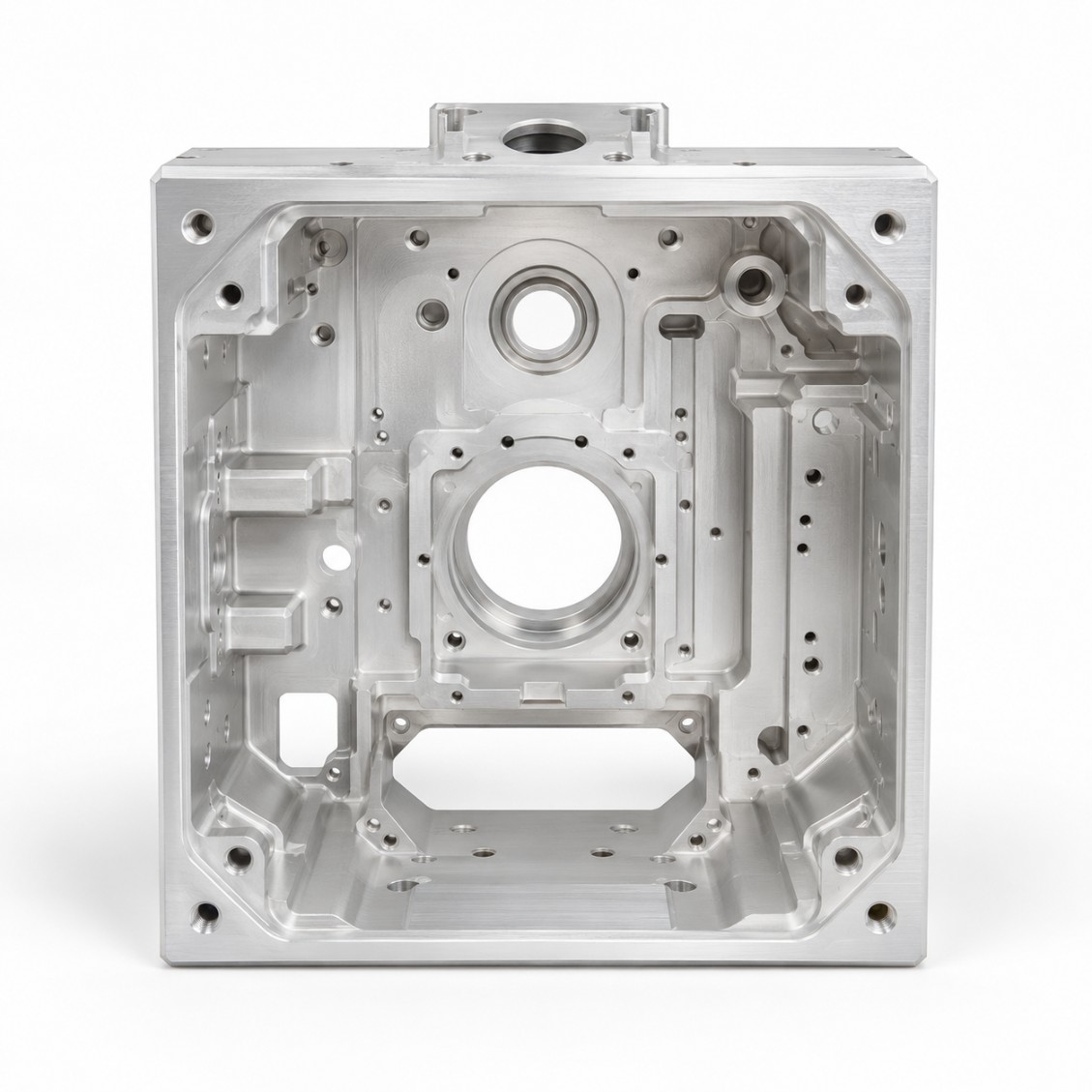 Al 7075 · Optical
 PEEK · Cleanroom
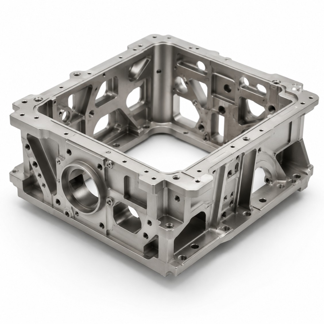 Ti Grade 5 · Aero