
Product Category
h4/h5 OD · ≤0.005/300 Straight · Ra 0.2µm · CMM
PS / 001 — 008
High-Straightness Ground
Positioning Shafts
Precision CNC ground positioning shafts for zero-backlash linear and rotary positioning systems. OD tolerance h4 / h5, straightness ≤ 0.005 mm / 300 mm, Ra 0.2 µm — engineered for precision linear actuators, ball-spline drives, CMM probes, optical bench positioners, and measurement instruments.
h4 / h5
OD Tolerance
≤0.005mm
Per 300 mm Straight
Ra 0.2µm
Ground Finish
PART DWG · PS-000 LINEAR-STAGE POSITIONING SHAFT · GCr15 HRC 62
ISO 9001 · BETWEEN CENTERS · CMM
≤0.005 mm / 300
h4 / h5 · Ra 0.2µm
Linear Stage · CMM · Optical · Lab Robot · Aero
Applications
GCr15 · 42CrMo4 · SUS440C · 316L · Al 7075 · Ti Gr5
Materials
48hr Quote · 5-Day Proto
Service
h4 / h5
OD Tolerance
positioning grade
positioning grade
≤0.005mm
Straightness
per 300 mm length
per 300 mm length
Ra 0.2µm
Ground Finish
smooth sliding surface
smooth sliding surface
5 Days
Fastest Delivery
prototype shafts
prototype shafts
Our Work
Request Similar Part →
Positioning Shafts We Have Made
Precision CNC machined positioning shafts for automotive, robotics, aerospace, medical, and industrial applications.
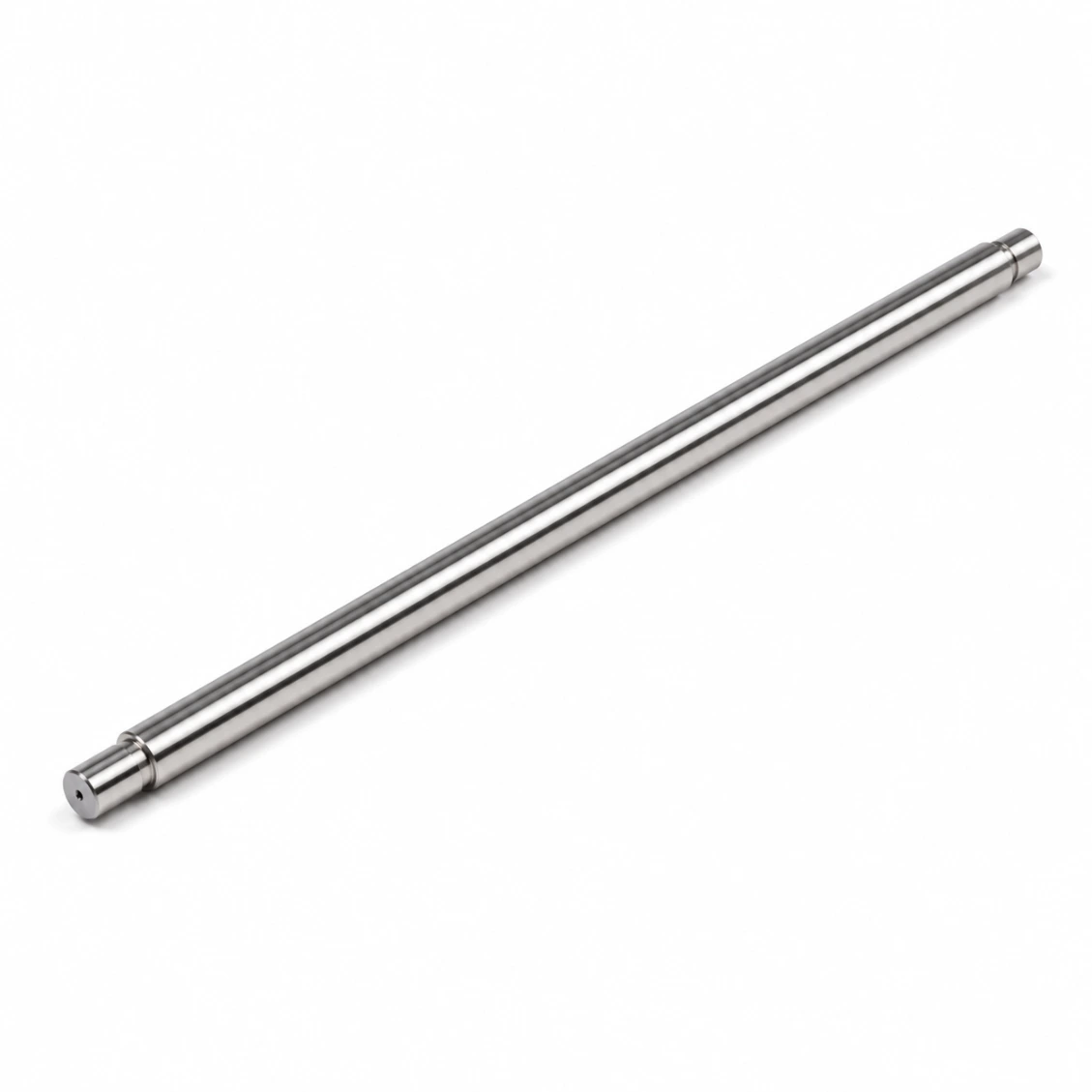 SUS303 · Linear
Positioning Shaft — Linear Stage
Ø12h5 · L=400mm · Ra 0.2µm · 50 pcs
 42CrMo4 · CMM
Positioning Shaft — CMM Probe
Ø8h4 · Hardened · 20 pcs
 Al 7075 · Optical
Optical Bench Positioning Shaft
Ø10h5 · Anodized · 30 pcs
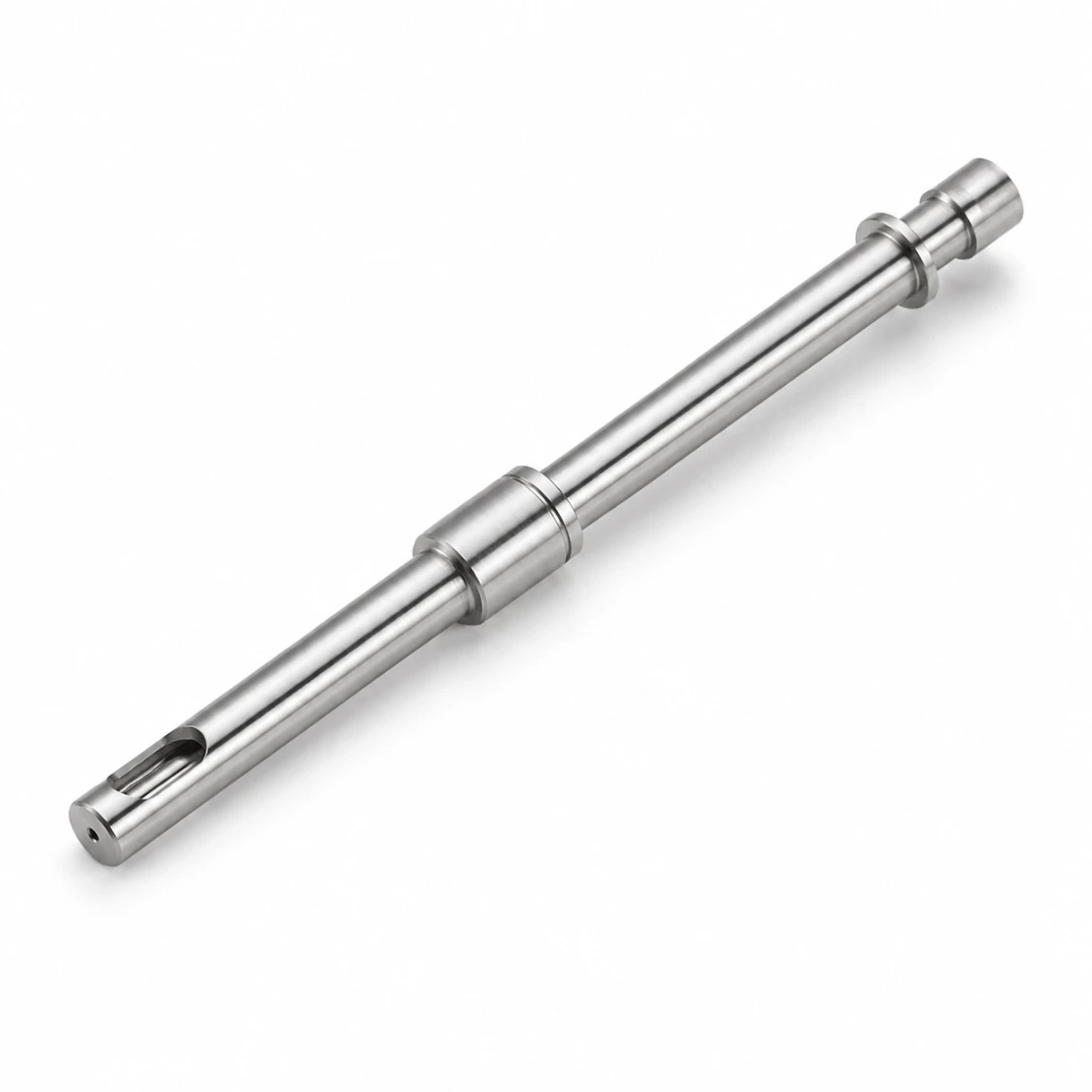 SUS316L · Med
Positioning Shaft — Lab Robot
Ø6h5 · Passivated · 40 pcs
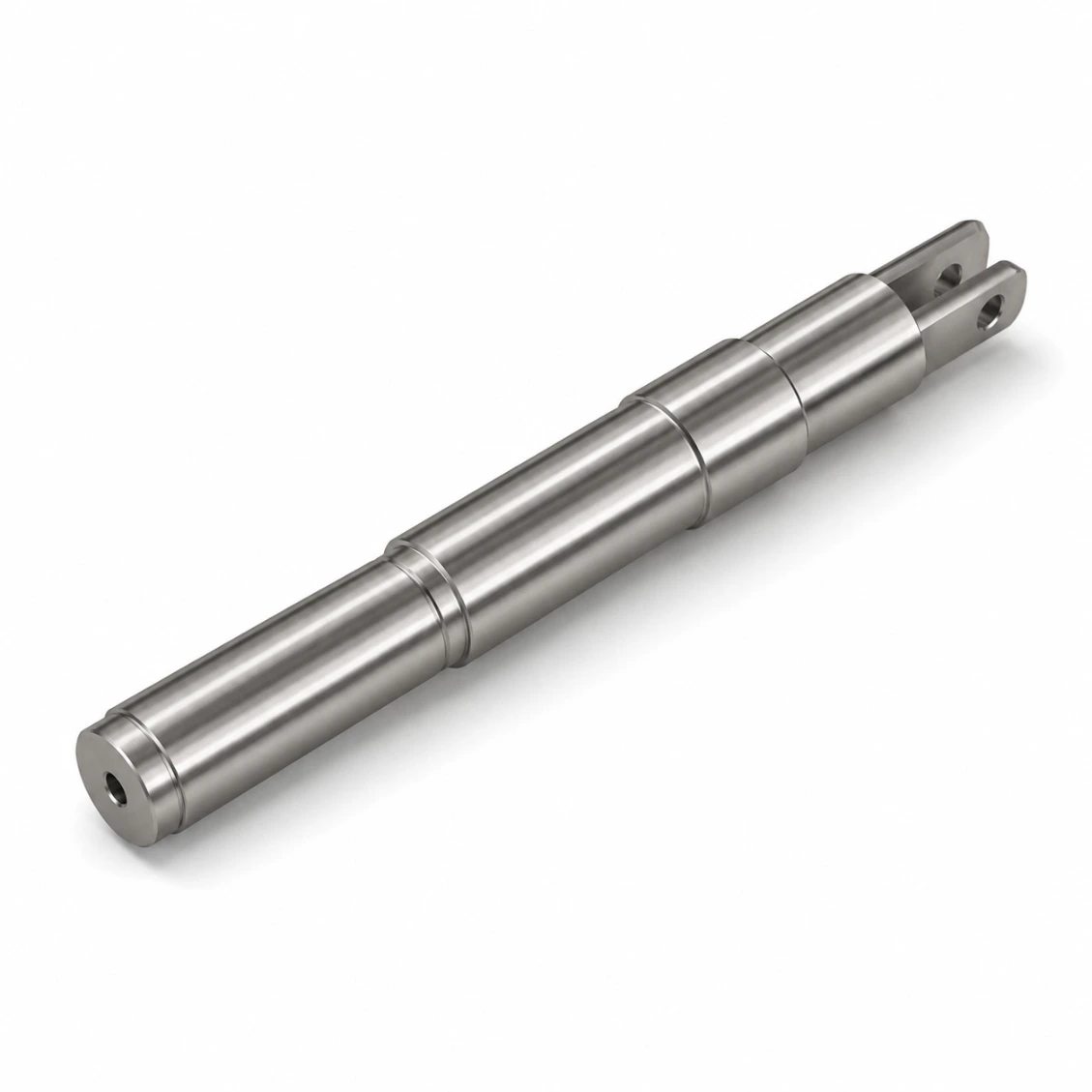 Ti Grade 5 · Aero
Positioning Shaft — Aero Actuator
Ø14h5 · ±0.002mm straight · 10 pcs
 GCr15 · Ball
Positioning Shaft — Ball Spline
Ø16h4 · GCr15 HRC62 · 100 pcs
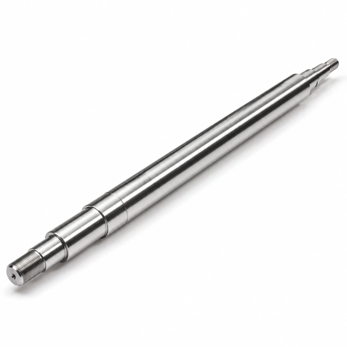 42CrMo4 · Servo
Linear Servo Positioning Shaft
Ø20h5 · L=600mm · 60 pcs
 CMM Verified
Straightness & OD Full Report
Every shaft straightness plotted
How It Works
From Drawing to Finished Part
Upload your drawing — material, tolerances, and surface treatment. Quote in 48 hours.
01
Upload Drawing
STEP, DXF, PDF, or sketch with key dimensions and tolerances.
02
Quote in 48h
Material, process, surface treatment, and firm lead time.
03
CNC Machine & Inspect
Precision turning, grinding, CMM verification, surface treatment.
04
Ship Worldwide
Full dimensional report. DHL / FedEx / sea freight.
Reviews
Trusted Positioning Shafts Manufacturer
★★★★★
"Excellent dimensional consistency across every batch. CMM report matched our incoming inspection perfectly. Lead time as promised."
AK
Alex K.
Mechanical Engineer · Germany
★★★★★
"HXC's DFM review caught two design issues before production. Finished parts were perfect first time. Strongly recommended."
SL
Sophie L.
Design Engineer · France
★★★★★
"Three years sourcing precision shafts from HXC. Quality consistent, lead times reliable, engineers always responsive."
JT
James T.
Senior Engineer · UK
FAQ
Positioning Shafts — Frequently Asked Questions
Technical and sourcing questions answered by our engineers.
A positioning shaft is a precision-ground shaft used in a linear or rotary positioning system where the shaft itself determines the axis of motion. Unlike a simple shaft that transmits torque, a positioning shaft guides a carriage, probe, or tool along a defined path — so its straightness, surface finish, and dimensional accuracy directly determine the positioning accuracy of the system. Common applications: linear stage shafts, CMM probe extensions, optical bench motion shafts, ball-spline drives, and actuator rods.
Cylindrical grinding between centres achieves straightness ≤ 0.005 mm per 300 mm as standard. For longer shafts or tighter requirements, incremental grinding passes are used. Shafts are measured for straightness using a CMM in a V-block fixture — the full straightness error plot is included on the inspection report. For ultra-precision positioning stages requiring straightness below 0.001 mm/300 mm, discuss with our engineers — this requires specialised lapping operations.
Positioning shafts often run in linear bushings or ball-spline nuts. The shaft Ra directly affects: bearing preload consistency (rough shafts cause variable ball contact load); sliding friction (rough shafts cause stick-slip in plain bushings); and bore wear rate (rough shafts abrade the bushing bore faster). Ra 0.2 µm is standard; Ra 0.1 µm is available for applications requiring minimum friction variation.
A positioning shaft is held to tighter straightness tolerance (as well as diameter and finish) because it defines a geometric axis rather than just transmitting force. A standard transmission shaft needs strength and fit tolerances at its bearing seats, but its mid-span straightness is less critical. A positioning shaft may also be longer relative to its diameter, making heat-treatment distortion and straightness correction the dominant manufacturing concern — every shaft is ground between dead centres and re-measured post-HT.
Prototype (1–5 pcs, hardened + ground between centres): 5–8 days. Small batch (10–50 pcs): 8–12 days. Production (100–1,000 pcs): 10–16 days. Stainless or titanium: add 2–4 days. Shafts over 600 mm: add 2–3 days for straightness correction. Rush production available.
GCr15 (SUJ2 / 100Cr6) through-hardened bearing steel — the premium choice for ball-spline shafts and matched-bearing linear stages, HRC 60–62. 42CrMo4 (induction hardened) for general linear actuators and servo positioning. SUS440C hardenable stainless for clean-room and vacuum-chamber stages. SUS303/316L for chemical, pharma, and lab automation. Al 7075 hard-anodized for optical-bench positioning. Ti Grade 5 for aerospace actuators.
Standard ground OD: Ra 0.4 µm. Precision linear bushing surface: Ra 0.2 µm. Mirror finish for low-friction or vacuum applications: Ra 0.1 µm. All measured by contact profilometer and reported on the inspection certificate.
Yes — end-machined features such as flats, threaded ends, keyways, cross-holes, and tapered shoulders for clamp mounting can all be added in the same 5-axis setup. Concentricity between integrated features and the ground sliding length stays within 0.003 mm TIR.
Maximum length between centres: 1,500 mm. For shafts over 600 mm, straightness correction after heat treatment is performed before final grinding to keep ≤ 0.005 mm/300 mm. For shafts over 1,000 mm, specify the full-length straightness limit (typically ≤ 0.02 mm over the full length) on your drawing — long shafts are inspected on a granite surface plate with dial indicator in addition to the V-block CMM check.