info@hxcnc.com Shenzhen, China Reply within 24 hours
ISO 9001 : 2015 Get Instant Quote
Product Category
IT5 Joint · ≤0.005mm Runout · −45% Weight · Hollow
RAL / 001 — 008

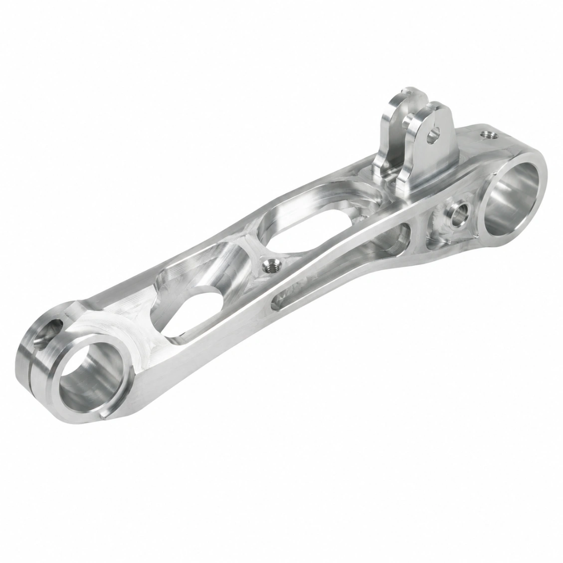
Lightweight CNC Machined
Robot Arm Links

Custom precision robot arm links — hollow tubular and prismatic designs in Al 7075 and Ti Grade 5. Joint interface bores IT5, end-flange runout ≤ 0.005 mm, minimum weight with maximum torsional stiffness. For 6-DOF industrial, collaborative, and custom robotic arms.

IT5
Joint Bore
≤0.005mm
Flange Runout
−45%
vs Solid
PART DWG · RAL-000 UPPER ARM LINK · Al 7075-T6 HA ISO 9001 · MOQ 1 PC
Joint Bore IT5
Hollow Tube
L ±0.05 mm ∥ 0.01 / 100 mm J1 J2 HOLLOW · POCKET UPPER ARM LINK · IT5 BORE · HOLLOW SECTION · TYPE SOLID 100% HOLLOW 55% RECT ◀ SCARA END FLANGE · RUNOUT ↗ ≤ 0.005 mm flange to bore ∥ 0.01/100mm ✓ CMM 100% ✓ matched pairs WEIGHT · STIFF 100% SOLID 55% POCKET 90% STIFF −45% inertia MATERIAL · ROBOT CLASS MATERIAL ρ g/cm³ USE Al 7075-T6 ◀ 2.81 cobot std Ti Grade 5 4.43 aero high-perf Al 6061-T6 2.70 research SCARA Al 2024-T3 2.78 fatigue duty CFRP + Al 1.55 hybrid ultra SCALE 1 : 4 · MM
Cobot · Industrial · Aero · Med · Service · SCARA
Use Cases
Al 7075 · 6061 · Ti Gr5 · CFRP Hybrid
Materials
48hr Quote · 7-Day Proto
Service
IT5
Joint Interface
bore tolerance class
≤0.005mm
End Flange Runout
concentricity
−45%
Weight vs Solid
hollowed Al 7075
7 Days
Fastest Delivery
prototype orders
Why It's Difficult

Robot Arm Link Challenges

A robot arm link must be simultaneously stiff (resist bending under payload), light (minimise motor torque demand), and accurate (interface bores and flanges concentric for zero backlash).

⚖️
Weight vs Stiffness
Rotational inertia of the link multiplied by gear ratio² determines the servo motor demand. HXC optimises wall thickness and hollow profile to achieve maximum stiffness per gram.
⦿
Interface Concentricity
Both end bores must be concentric and parallel within tolerance — any misalignment creates a kinematic error in the robot's reach. All interface features are machined in one setup.
Torsional Strength
Robot arm links carry torsion from wrist torque reactions. Tube wall thickness, rib placement, and cross-section shape are designed to maximise torsional stiffness without adding weight.
Our Work

Robot Arm Links We've Made

Upper arm, forearm, and wrist link components for collaborative and industrial robots.

Request Similar Part
Upper Arm Link — Collaborative Robot
Forearm Link — Industrial 6-DOF
Aerospace Robot Arm Link
SCARA Arm Link
Surgical Robot Arm Link
Service Robot Arm Segment
Research Robot Arm Link
Production Batch — Arm Links
Capabilities & Tolerances

What We Can Deliver

Typical specifications for this product type. Confirm exact requirements at enquiry.

Joint bore tol.IT5
Flange runout≤ 0.005 mm
Arm length tol.±0.05 mm
Parallelism≤ 0.01 mm / 100 mm
Weight reduction40–50% vs solid
Min wall thickness2 mm (load zones)
MaterialsAl 7075, Al 6061, Ti Gr5, CFRP hybrid
Cross-sectionCircular, rectangular, pocket-milled
Surface treatmentType II / III anodize, passivate
MOQ1 pc (prototype)
Lead time (proto)7–10 days
Lead time (production)18–28 days
How It Works

From Drawing to Finished Part

Upload your 2D/3D file — receive DFM feedback, quote, and confirmed lead time within 48 hours.

01
Upload Drawing
STEP, DXF, PDF or sketch. 2D + 3D preferred.
02
DFM Review & Quote
Free DFM feedback + material, lead time, and cost — within 48 hours.
03
CNC Machining & QC
5-axis CNC, CMM inspection, full dimensional report.
04
Ship Worldwide
DHL / FedEx / sea freight. Inspection report enclosed.
Reviews

Trusted by Engineers Worldwide

★★★★★
"The CMM report matched our incoming inspection perfectly. Every critical dimension was within spec on the first article. Lead time exactly as quoted."
AK
Alex K.
Mechanical Engineer · Germany
★★★★★
"HXC's DFM review caught a tolerance stack issue before we committed to production. The finished parts were perfect and batch consistency was excellent."
SL
Sophie L.
Design Engineer · France
★★★★★
"We've sourced over 30 part numbers from HXC across three years. Quality is consistent, lead times are reliable, and the engineering team is always responsive."
JT
James T.
Senior Buyer · UK
FAQ

Robot Arm Link — FAQ

Common questions from engineers and procurement teams — answered by our manufacturing team.

A robot arm link is the structural segment between two robot joint housings — it transmits the torque and forces generated at each joint to the next, while minimising rotational inertia seen by the servo motors. The link's end-interface bores must be concentric, parallel, and at the correct distance to achieve the robot's reach specification.
For a 6-DOF robot, link inertia is reflected through the gear ratio² of each upstream joint. Reducing link weight by 30% allows the joint motor to accelerate the arm faster, extend the reach, or handle a larger payload with the same motor. HXC calculates the inertia reduction achievable from hollowing before quoting.
HXC offers: Circular hollow section (best torsional stiffness per weight); rectangular hollow (better bending stiffness in one plane — for SCARA arms); complex pocket-milled section (topology-optimised, maximum stiffness per gram, higher cost). The optimal section is selected during DFM review based on your arm's load case.
Both end bores: IT5 tolerance class. End flange face runout to bore axis: ≤ 0.005 mm. Distance between end bores (arm length): ±0.05 mm. Parallelism between the two bore axes (determines robot kinematic accuracy): ≤ 0.01 mm per 100 mm of arm length — verified by CMM.
Yes — mirrored and scaled variants of an arm link design can be produced from the same CAD model family. HXC can produce a set of 3–4 link sizes (scaled versions) with consistent interface standards and verified CMM reports — useful for modular robot arm platforms.
Al 7075-T6 hard anodized: standard for collaborative robots — 2.8 g/cm³, high strength, excellent machinability. Ti Grade 5: aerospace and high-performance cobots — 30% lighter than Al 7075 for the same stiffness, higher cost. CFRP with machined Al inserts: highest specific stiffness — hybrid design available.
Yes — symmetric arm link pairs are produced from the same CMM program with left/right mirror symmetry verified. All critical interface dimensions (bore diameter, flange face runout, arm length) are matched to within the tolerance class specification.
Prototype: 7–10 days. Small batch (50–200 pcs): 12–18 days. Production: 18–28 days. Ti Grade 5 links add 3–5 days.
Get a Quote

Send Your Drawing.
Get a Quote.

Every enquiry includes a DFM review — tolerance feasibility, material confirmation, and process approach confirmed before production starts. MOQ 1 piece.

24hr
Quote Response
MOQ 1
Prototypes OK
ISO
9001:2015
📐
DFM Review on Every Enquiry
Tolerance feasibility, fixturing strategy, and material confirmation. Specific, actionable feedback — not generic pushback.
🎯
First Article Inspection — Standard
FAI report on every new run. Material certs and surface treatment certs included with every shipment.
🔄
Same Process: Prototype to Production
Process plan from your prototype applies to production batches. No re-qualification when you scale.
3 / 4 / 5-Axis CNC + Turning
Complex structural parts, shafts, housings, and transmission components. Metals and engineering plastics.
ISO 9001:2015 3/4/5-Axis Milling CNC Turning CMM Inspection Global Delivery