
Product Category
UAV / Optical / PTZ · 3-Axis Stabilised
GIM / 001 — 008
Precision CNC Machined
Gimbal Structures
Custom precision-machined gimbal structures — pivot bearing seats IT5, frame concentricity ≤ 0.005 mm, lightweight hollow Al 7075 or Ti Grade 5. For UAV camera gimbals, stabilised optical platforms, and precision pan-tilt systems.
IT5
Bearing Seat
≤0.005mm
Pivot Concentric
−55%
Mass Reduction
PART DWG · GIM-000 3-AXIS GIMBAL · Al 7075-T6
ISO 9001 · DJI/SIYI Compat
YAW · ROLL · PITCH
3-Axis Common Centre
Hollow · −55% Mass
Camera · Optical · LiDAR · PTZ
Gimbal Types
Al 7075 · Al 6061 · Ti Grade 5
Materials
48hr Quote · MOQ 1
Service
IT5
Bearing Seat
tolerance class
tolerance class
≤0.005mm
Pivot Concentricity
stabilisation accuracy
stabilisation accuracy
Al 7075
Material
hard anodized
hard anodized
7 Days
Fastest Delivery
prototype orders
prototype orders
Why It's Difficult
Gimbal Structure Challenges
Gimbal pivot accuracy directly determines stabilisation performance — any bearing-seat misalignment introduces a wobble that no control algorithm can fully compensate.
⦿
Pivot Bearing Concentricity
All three pivot axes must intersect at a common centre point within ≤ 0.01 mm. Bearing seats on the same
axis must be concentric to ≤ 0.005 mm — machined in a single setup.
⚖️
Moment of Inertia Balance
An unbalanced gimbal frame demands larger motors and faster control loops. HXC removes material
symmetrically from non-structural zones to minimise inertia imbalance without custom counterweights.
🔩
Motor Interface Accuracy
Gimbal motors have precise mounting flanges. Motor mount bore concentricity to the pivot axis must be
≤ 0.005 mm — verified by CMM — to prevent cogging due to air-gap variation.
Our Work
Request Similar Part →
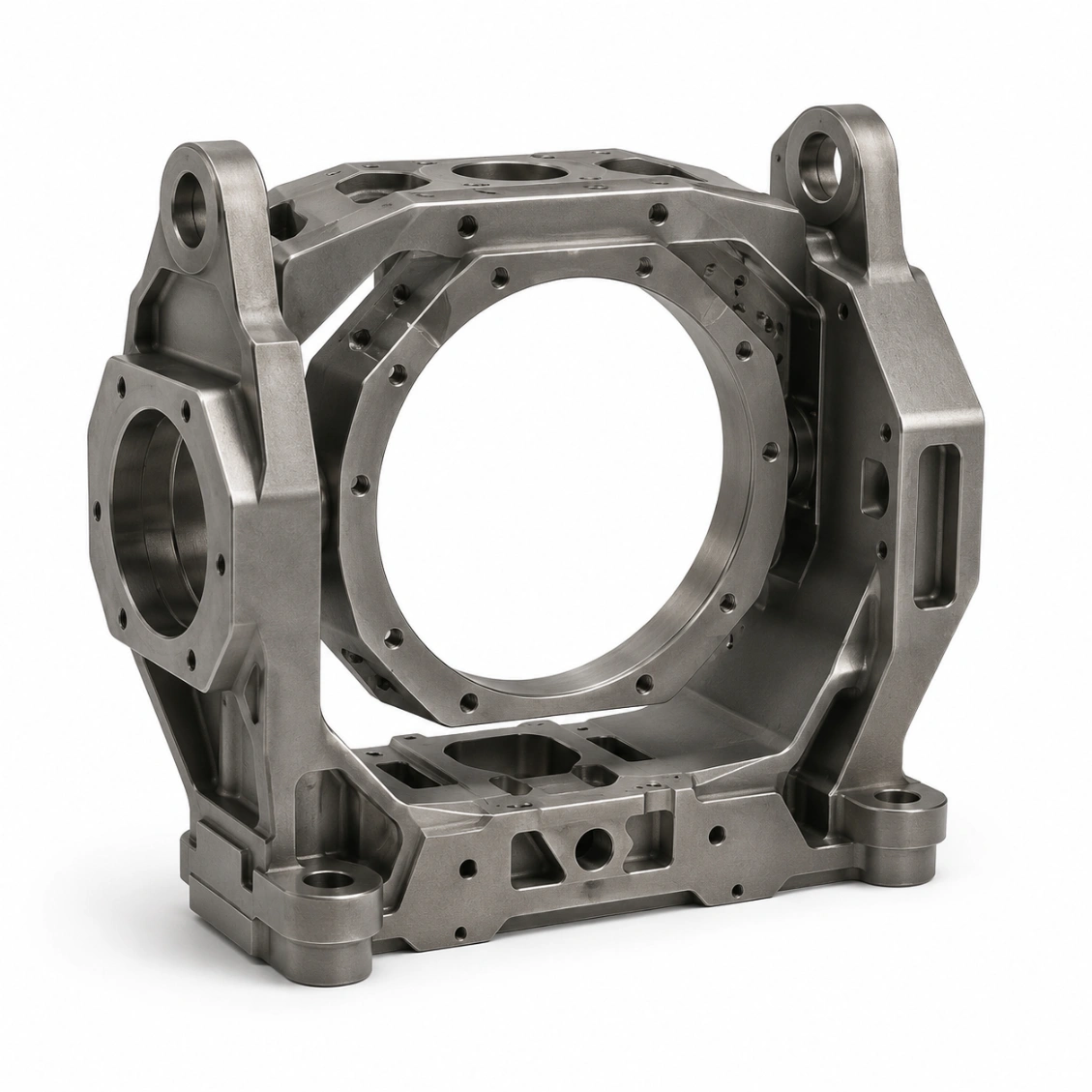
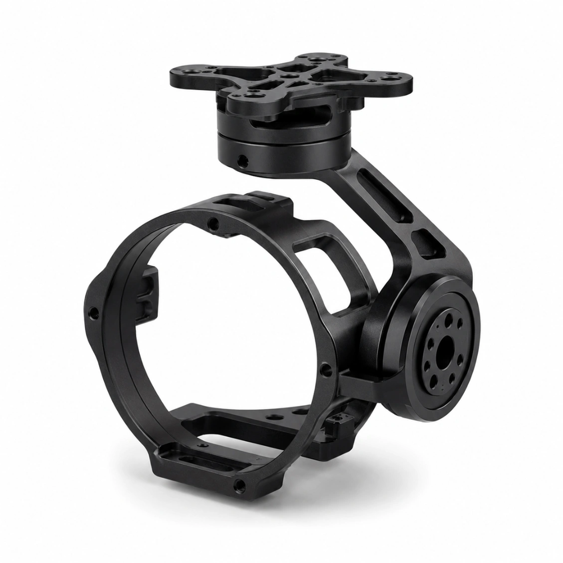
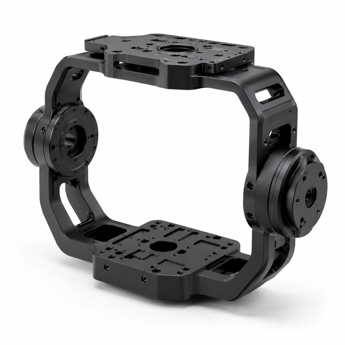
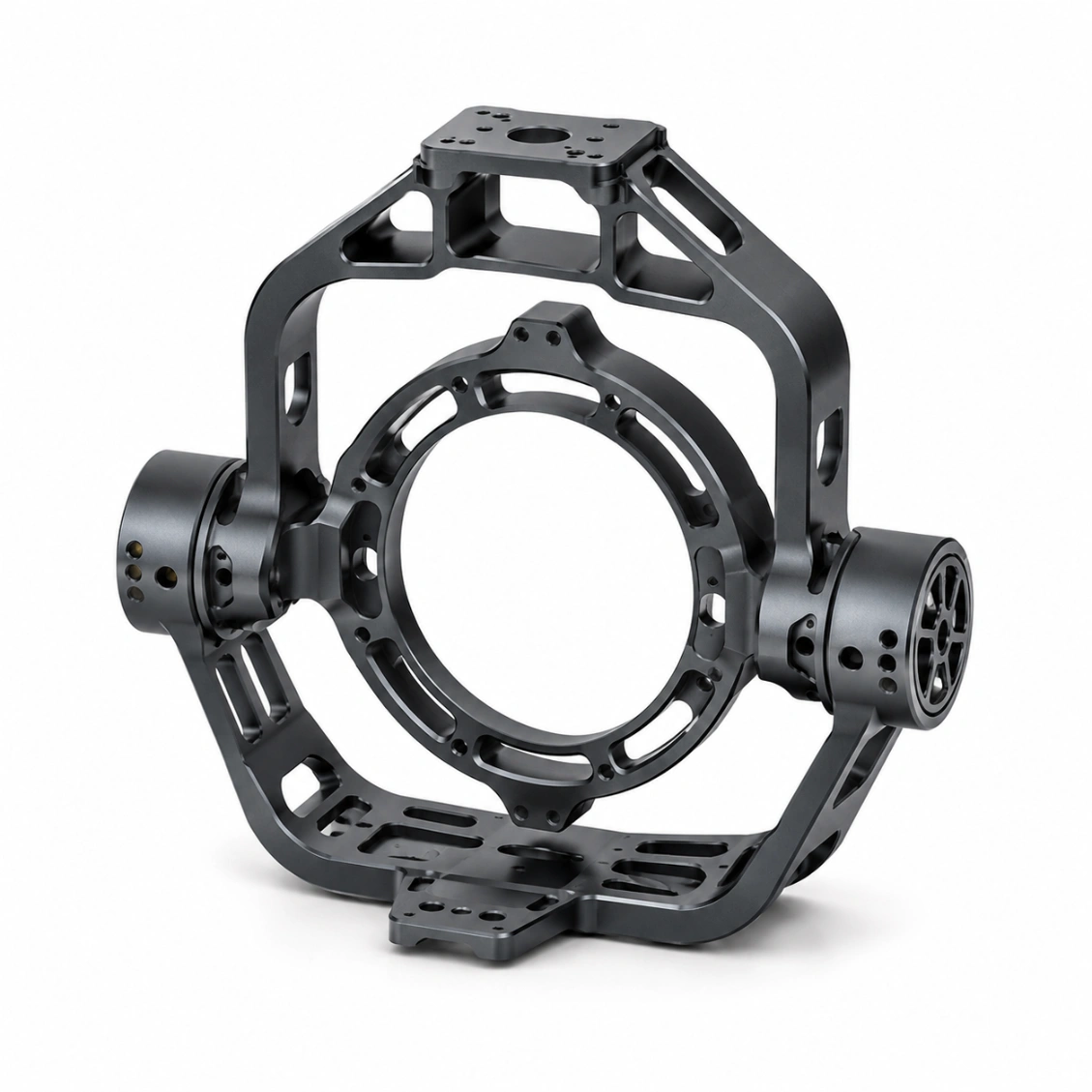
Gimbal Structures We've Made
Real projects — CMM verified.




How It Works
From Drawing to Finished Part
Upload your 2D/3D file — receive DFM feedback, quote, and confirmed lead time within 48 hours.
01
Upload Drawing
STEP, DXF, PDF or sketch. 2D + 3D preferred.
02
DFM Review & Quote
Free DFM feedback + material, lead time, and cost — within 48 hours.
03
CNC Machining & QC
5-axis CNC, CMM inspection, full dimensional report.
04
Ship Worldwide
DHL / FedEx / sea freight. Inspection report enclosed.
Reviews
Trusted by Engineers Worldwide
★★★★★
"The CMM report matched our incoming inspection perfectly. Every critical dimension was within spec on the first article. Lead time exactly as quoted."
AK
Alex K.
Mechanical Engineer · Germany
★★★★★
"HXC's DFM review caught a tolerance stack issue before we committed to production. The finished parts were perfect and batch consistency was excellent."
SL
Sophie L.
Design Engineer · France
★★★★★
"We've sourced over 30 part numbers from HXC across three years. Quality is consistent, lead times are reliable, and the engineering team is always responsive."
JT
James T.
Senior Buyer · UK
FAQ
Gimbal Structures — FAQ
Common questions from engineers and procurement teams — answered by our manufacturing team.
Camera gimbals: pivot bearing seats concentric to ≤ 0.005 mm. All three axis bearing
seats must be perpendicular to each other within ≤ 0.01 mm/100 mm. This ensures the
optical axis passes through a stable centre of rotation — critical for stabilisation accuracy. These
tolerances are verified by CMM and reported.
HXC uses symmetrical pocket milling — removing material from the inner surfaces of the
gimbal yokes while retaining full wall thickness at bearing seat zones, motor mounts, and structural
ribs. This typically reduces frame weight by 40–55% while retaining 95%+ of the torsional stiffness
needed for stabilisation.
HXC machines gimbal motor mounts for all standard brushless gimbal motors:
hollow-shaft motors (custom bore and flange), standard stator bolt
patterns, and direct-drive mounting faces. Provide the motor datasheet and we
machine to the manufacturer's interface specification.
Yes — inner, middle, and outer yoke frames are produced and CMM-verified as a matched set. All bearing
seat positions are verified relative to a common reference to confirm the three pivot axes are
orthogonal and pass through the nominal intersection point.
Al 7075-T6 hard anodized: standard for most UAV camera gimbals — 2.81 g/cm³, high
stiffness, non-reflective black anodized finish suppresses stray reflections. Al 6061:
lower cost, adequate strength for lightweight camera gimbals. Ti Grade 5: for defence,
marine, and demanding environments where higher specific stiffness is needed.
Type III hard anodized black (15–25 µm, HV 400+): non-reflective, wear-resistant, and
corrosion-resistant. The black finish also reduces stray light reflections into the camera sensor.
Dimensional pre-compensation is applied before anodizing.
Yes — for high-altitude and low-temperature environments (−40°C to −60°C operating range), HXC
recommends: Al 7075-T651 (better toughness at low temperature than T6);
Type III anodizing (enhanced environmental protection); Alodine 1200
conversion coating at bond interfaces. Discuss your environmental specification at enquiry.
Prototype: 7–10 days. Small production (100–500 pcs): 10–16 days. Large production:
14–22 days.