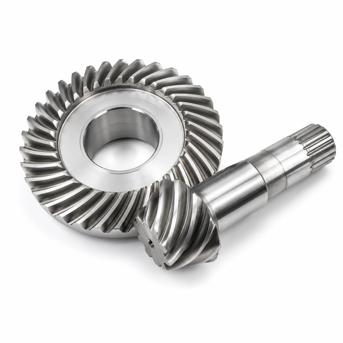
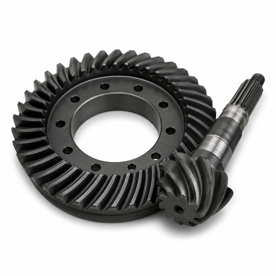
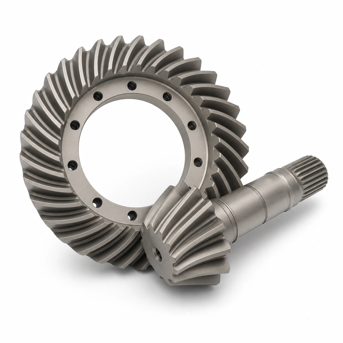
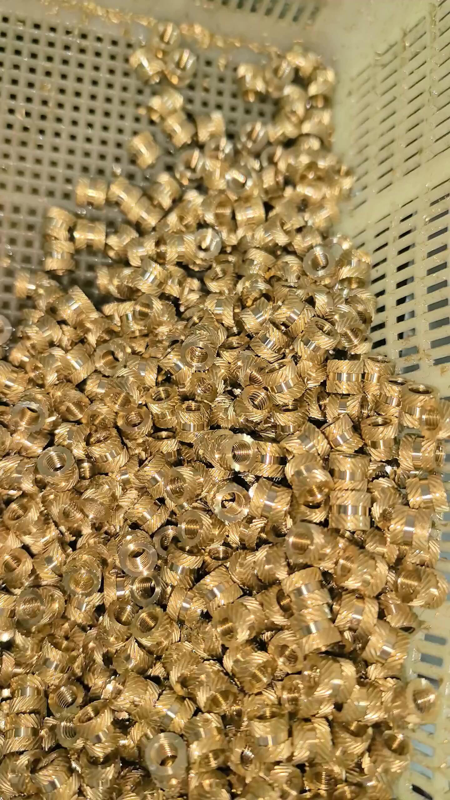
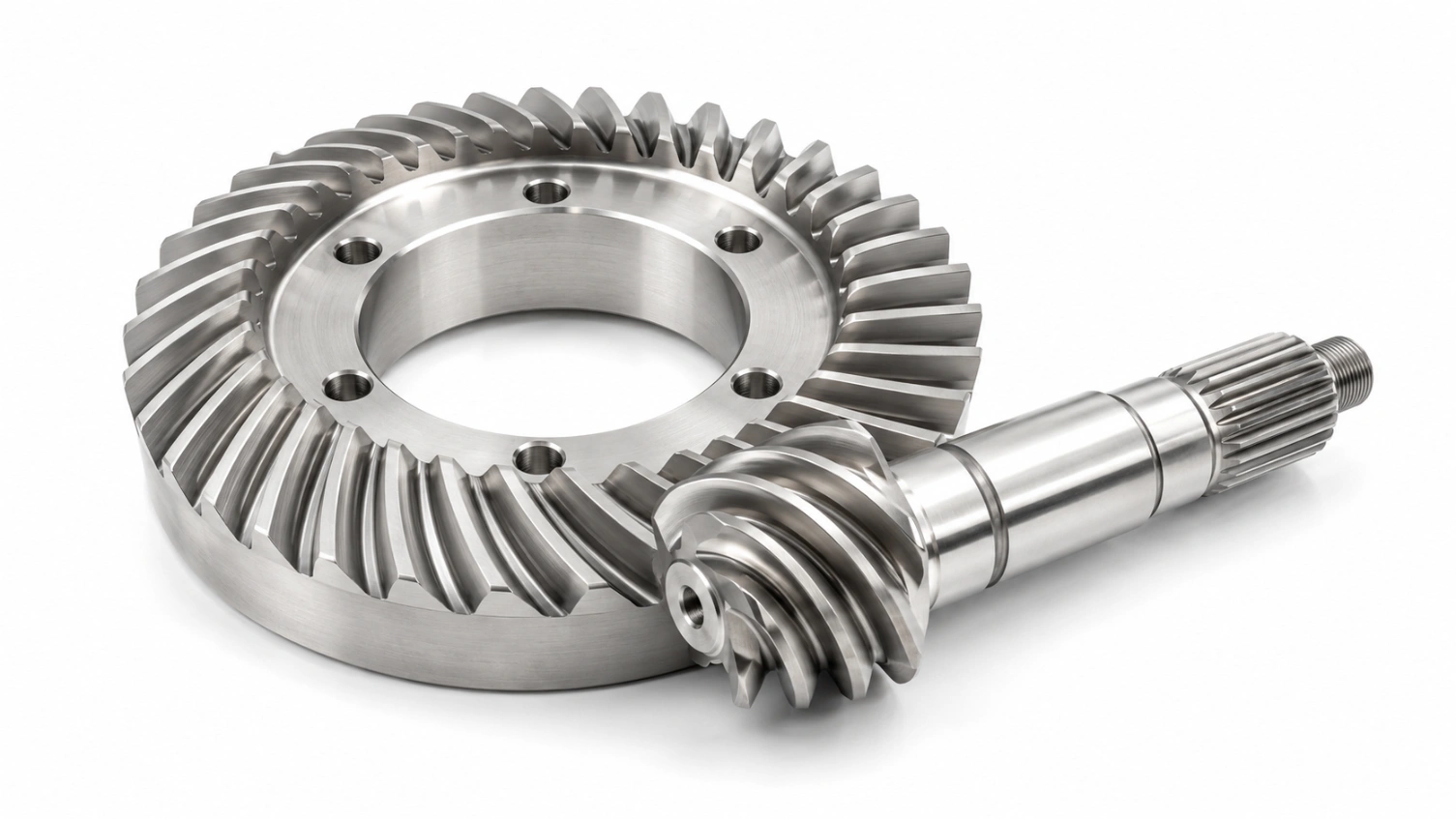
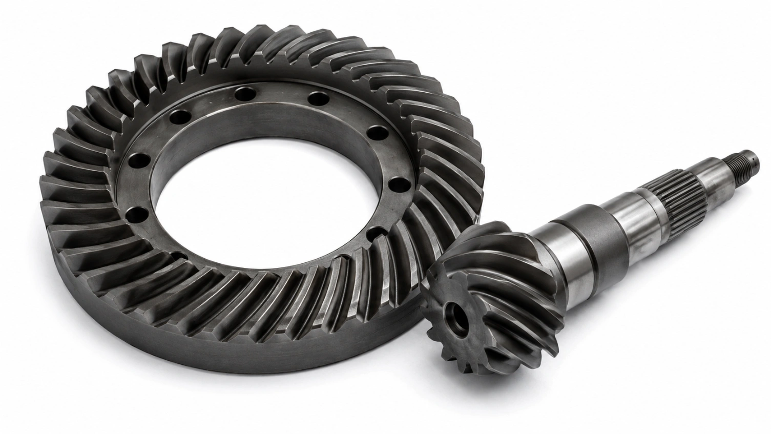
High-accuracy spiral bevel gears to Gleason and DIN standards. Module 1–16, any shaft angle, any spiral
angle — prototype to mass production, every piece fully CMM-inspected with contact pattern verification.
Four processes — from Gleason face-milled production bevel gears to ultra-precision lapped aerospace matched
sets.
⚙️
Face Milling (Gleason)
High-volume
🔬
Bevel Grinding
Ultra-precision
🏭
Lapping (Matched Sets)
Low noise / NVH
🔧
5-Axis CNC Milling
Prototype / custom angle
Face Milling — Gleason System
CNC Gleason face-milling machines generate the Duplex Taper tooth geometry standard in automotive
differentials and power-transmission bevel drives. Ideal for medium to high volume production of
matched pinion-and-ring sets.
Module range
1.5 – 16 mm
Max pitch dia.
600 mm
Shaft angle
45° – 135° (std. 90°)
Quality grade
DIN 6–9 standard
Tooth profile tol.
±0.012 mm
Typical quantity
50 – 20,000 pcs
Lead time
10 – 18 days
Materials
Steel, Al, Stainless
Bevel Gear Grinding
Post-cutting or post-hardening CBN grinding on dedicated bevel grinders. Achieves DIN 4–5 tooth
accuracy and Ra ≤ 0.4 µm flank finish for aerospace and precision instrument applications.
Module range
1 – 10 mm
Max pitch dia.
350 mm
Quality grade
DIN 4–6 precision
Tooth profile tol.
±0.006 mm
Surface finish Ra
0.2 – 0.6 µm
Post heat treatment
Yes — hardened grinding
Lead time
12 – 22 days
Materials
20CrMnTi, 42CrMo4, M2 HSS
Lapping — Matched Mating Sets
Gear lapping runs the pinion and ring gear together with abrasive compound to develop an optimal
contact pattern and minimise NVH. Matched sets are marked, packed, and delivered together for direct
assembly.
Module range
1.5 – 12 mm
Max pitch dia.
500 mm
Contact pattern
Per customer drawing
Noise reduction
3–8 dB vs. cut-only
Surface finish Ra
0.3 – 0.8 µm
Marking
Matched set serial number
Lead time
12 – 20 days
Common use
Automotive, marine drives
5-Axis CNC Milling
Custom spiral bevel gears with non-standard shaft angles, integrated flanges, or one-off geometries
machined complete in a single 5-axis setup. Ideal for prototypes and low-volume special designs.
Module range
2 – 16 mm
Max pitch dia.
480 mm
Shaft angle
Any — fully programmable
Quality grade
DIN 7–9
Tooth profile tol.
±0.018 mm
MOQ
1 pc
Lead time (proto)
7 – 12 days
Materials
All metals + engineering plastics
Materials
50+ Certified Materials
Full mill certificates and spectral analysis on every batch.
Metals
Engineering Plastics
SUS316L Stainless
Marine, food-processing and medical-grade spiral bevel applications.
MarineFood Grade
42CrMo4 Alloy Steel
Through-hardened, excellent fatigue and impact resistance for heavy drives.
Heavy DutyIndustrial
Al 7075-T6
Higher strength than 6061, anodizable. Aerospace and UAV drivetrains.
LightweightAerospace
C36000 Brass
Free-machining, low-noise, excellent for instruments and light-duty bevel drives.
Low NoiseInstruments
20CrMnTi Steel
Case-hardened, HRC 58–62 surface, tough core. Industry standard for automotive bevel gears.
High LoadHardened
POM (Delrin)
Self-lubricating, dimensionally stable. Light-duty bevel drives with low noise.
Self-lubricatedLow Noise
Nylon PA66-GF30
30% glass-filled for higher stiffness. Reduced creep under sustained load.
High StrengthLightweight
PEEK
Chemical-resistant, rated to 260°C. Sterilizable medical-grade bevel gears.
High TempChemical Res.
Case Studies
Real Projects, Real Results
Selected orders showcasing our range — from single prototypes to 5,000+ matched-set production runs.
Automotive
Rear Axle Differential Bevel Set
Material
20CrMnTi
Process
Gleason + Lap
Quantity
1,500 sets
Lead Time
18 days
✓ Contact pattern approved in 1 cycle · zero warranty returns
Aerospace
UAV Gearbox Spiral Bevel Set
Material
Ti-6Al-4V
Process
5-Axis + Grind
Quantity
40 sets
Grade
DIN 5
✓ FAI approved first cycle · full CMM report enclosed
Marine
Marine Steering Bevel Gear Pair
Material
SUS316L
Process
Face Mill + Passivate
Quantity
120 sets
Lead Time
14 days
✓ DNV material certs supplied · salt-spray tested 500 h
How It Works
From Drawing to Your Door
Upload your CAD file or Gleason summary sheet — we handle everything from DFM to contact pattern
validation and global shipping.
01
Upload CAD / Drawing
STEP, IGES, DXF, DWG, Gleason summary sheet, or PDF tooth data — any format accepted.
02
Quote in 48 Hours
Process recommendation, material selection, contact ratio analysis, and firm lead time with cost breakdown.
03
Machining & Contact Check
CNC gear cutting with in-process Klingelnberg measurement and contact pattern verification before shipment.
04
Ship Worldwide
Vacuum-packed matched sets with serial numbers, full inspection report enclosed. DHL / FedEx / sea freight.
Quality
Zero-Defect Commitment
Every spiral bevel gear passes a 4-stage inspection protocol, including contact pattern verification, before
leaving our facility.
Certifications & Equipment
✓
ISO 9001:2015
Quality Management System — all processes certified
📐
Gleason / DIN Standards
DIN 3965 tolerance classes 4–10, Gleason geometry calculation available
Mill cert + spectral analysis on every material batch; third-party certs available
4-Stage Inspection Protocol
1
Incoming Material Check
Spectral analyzer verifies alloy grade and heat number before any machining begins.
2
First Article Inspection
Full CMM measurement of the first gear — all critical dimensions confirmed before batch production starts.
3
Contact Pattern Verification
Klingelnberg tester confirms tooth contact pattern location and shape against the customer-approved target area.
4
Final Outgoing Inspection
100% visual + sampled CMM. Full measurement report and contact pattern photograph shipped with every order.
Reviews
Trusted by Engineers Worldwide
★★★★★
"1,500 matched bevel sets for our rear-axle assembly line. Contact pattern was perfect on every set — passed our incoming inspection first time with zero reworks. Consistent lot to lot."
TF
Thomas F.
Drivetrain Engineer · Germany
★★★★★
"Prototype titanium spiral bevel gears for our UAV gearbox arrived in 9 days. CMM report was thorough. FAI approved first cycle and we are now in series production with HXC."
LB
Lena B.
Systems Engineer · Netherlands
★★★★★
"Marine stainless bevel gears that needed DNV material certs. HXC provided full documentation and the gears passed our salt-spray test without a single issue. Delivery exactly on schedule."
PK
Piotr K.
Procurement Manager · Poland
FAQ
Frequently Asked Questions
Everything engineers and buyers ask about spiral bevel gears — answered by our manufacturing team.
A spiral bevel gear is a bevel gear whose teeth are cut along a curved, oblique path across the gear
cone face — as opposed to the straight radial teeth of a straight bevel gear. The curved tooth
produces a gradual, overlapping tooth engagement rather than an abrupt line contact,
which gives spiral bevel gears their characteristic advantages: higher load capacity, lower noise, and
smoother operation. They are used wherever power must be transmitted between intersecting shafts —
almost always at 90°, though other angles are possible.
Both types transmit power between intersecting shafts and share the same conical geometry. The
difference is the tooth form: straight bevel gears have teeth that point directly at
the cone apex — simple to make but noisier and lower in load capacity. Spiral bevel
gears have curved, oblique teeth that engage gradually, giving them 20–40% higher load
capacity for the same size, much lower noise (typically 10–15 dB quieter), and higher pitch-line
velocity capability. The trade-off is greater manufacturing complexity and the need for a thrust
bearing to handle the axial load that the spiral angle generates.
The spiral angle (β) is the angle between the tooth trace at the pitch cone and a generator of the
pitch cone. It determines the degree of obliqueness of the teeth. Standard spiral angle is
35° in Gleason-system gears — a value that balances load capacity, axial thrust, and
manufacturability. Higher spiral angles increase the contact ratio (smoother operation) but also
increase axial thrust. Angles from 25° to 45° are common; the Gleason system uses a mean spiral angle
of 35° as the default for most automotive and industrial designs.
"Gleason" refers to the tooth geometry system developed by the Gleason Works (Rochester, NY) for bevel
and hypoid gears — the dominant standard in automotive and industrial gearing worldwide. Gleason
spiral bevel gears use a face-milling process that generates a tapered tooth depth
(Duplex Taper), with the tooth taper matched between the ring gear and pinion. The Gleason system
defines all parameters: cutter radius, spiral angle, pressure angle, tooth taper type, and the
calculation methods for tooth contact. An alternative system is Klingelnberg
(Palloid), which uses a continuous face-hobbing process producing a uniform tooth depth.
Both look similar but differ in shaft geometry: spiral bevel gears have intersecting
axes — the pinion axis and ring gear axis cross at a point. Hypoid gears have offset
(non-intersecting, non-parallel) axes — the pinion axis is offset below (or above) the ring gear axis.
Hypoid gears allow the pinion to be larger and stronger for the same ring gear size, enable the
driveshaft to be lower (used in most automotive rear axles for lower floor height), and can carry
more load, but are less efficient due to sliding action and require extreme-pressure (EP) gear oil.
Spiral bevel gears are simpler, more efficient, and preferred when axis offset is not needed.
Spiral bevel gears are the standard solution anywhere power must change direction between
intersecting shafts: automotive differentials, transfer cases, and PTOs;
aerospace helicopter accessory gearboxes and actuator drives; marine
steering gear and thruster drives; heavy industry right-angle drives for mixers,
conveyors, and milling machines; robotics wrist joints and camera pan-tilt systems;
and agriculture power take-off gearboxes. Any application combining high torque,
moderate to high speed, and an intersecting-shaft layout is a natural candidate.
Key advantages over straight bevel gears: higher load capacity (20–40% more for the
same size — overlapping tooth contact distributes load better); lower noise and
vibration (gradual engagement, typically 10–15 dB quieter); higher pitch-line
velocity capability (straight bevel gears are limited to about 5 m/s; spiral bevel gears
operate smoothly above 40 m/s); smoother torque transmission — no impact loading;
and longer service life under cyclic loading. The main trade-offs are higher
manufacturing cost and axial thrust loads requiring thrust bearings.
The main limitations are: higher manufacturing complexity and cost — cutting requires
specialised Gleason or Klingelnberg machines, not standard hobbers; axial thrust load
— the spiral angle generates a significant axial force component that must be absorbed by thrust
bearings, adding housing complexity; contact pattern sensitivity — precise mounting
distance and bearing preload are critical, deviations alter the contact pattern and reduce gear life;
hand of spiral matters — left-hand and right-hand pinions are not interchangeable;
and lapping is often required for automotive applications to optimise the contact
pattern, adding a process step.
The contact pattern is the area of a bevel gear tooth flank that actually transmits load during
meshing. It is visualised by applying a thin marking compound to the teeth and rolling the gear pair
under light load — the compound transfers to the mating tooth, revealing the contact zone.
An ideal contact pattern is centred on the tooth face, slightly biased toward the toe (small
end) under no-load, and moves toward the heel (large end) under full load. Patterns that are
too close to the toe or heel concentrate stress and cause premature wear or fatigue. Contact pattern
verification is a mandatory step in HXC's outgoing inspection for all bevel gear orders.
The hand of spiral describes which direction the teeth curve across the cone face. Viewed from the
back of the gear, right-hand (RH) teeth curve clockwise away from the apex;
left-hand (LH) teeth curve anti-clockwise. A right-hand pinion always meshes with a
left-hand ring gear and vice versa — they are not interchangeable. Hand of spiral also determines the
direction of the axial thrust force: under driving load, a right-hand pinion generates thrust away
from the apex. This must be specified on the drawing and matched to the bearing arrangement. HXC
machines both hands to order; please specify on your drawing or inquiry.
The most common pressure angles in Gleason spiral bevel gears are 20° and 22.5°. A
20° pressure angle is standard for most industrial and automotive gears. A 22.5° pressure angle
increases tooth root strength and reduces the tendency for the tooth root to undercut at low tooth
counts. 20° is the default at HXC; 22.5° and 25° are available on request. Higher
pressure angles increase the normal force on the tooth (and therefore bearing loads) but allow
shorter, stronger teeth. The pressure angle must match between pinion and ring gear — it cannot be
mixed.
Spiral bevel gears can be produced in virtually any ratio, but practical single-stage ratios
range from 1:1 to approximately 8:1. Ratios above 8:1 are possible but the pinion becomes
very small with few teeth, making it structurally weak; a two-stage arrangement is usually preferred
beyond 8:1. The most common range is 1.5:1 to 5:1. At 1:1 ratio (miter gears) the
set is symmetric and both gears are identical — very common in instrument and robot wrist drives. HXC
can calculate the optimal tooth numbers for any required ratio; simply state your ratio and shaft
speed in the enquiry.
A miter gear is simply a bevel gear with a 1:1 ratio — both gears are the same size
and have the same number of teeth. They are used to change shaft direction by 90° without changing
speed. Because both gears are identical, a miter gear set is the most economical bevel design (one SKU
instead of two). They can be straight, spiral, or zerol bevel forms. Spiral miter gears offer the
same noise and load capacity advantages as other spiral bevel gears and are common in right-angle
drives for instrumentation, robotics, and compact industrial gearheads.
Zerol bevel gears are a special case: they have curved teeth like spiral bevel gears but a
zero mean spiral angle — the teeth curve across the face but are tangent to the
pitch cone generator at the midpoint. This means zerol bevel gears have no net axial thrust
load (an advantage over spiral bevel), while retaining the gradual tooth engagement and
lower noise of curved teeth (an advantage over straight bevel). The trade-off is lower load capacity
than spiral bevel gears of the same size, because the contact ratio is lower. Zerol bevel gears are
mainly used in aircraft accessories and instrument drives where eliminating axial thrust is more
important than maximising load capacity.
For the highest contact and bending fatigue life — automotive and industrial drives —
case-hardened 20CrMnTi (carburised to HRC 58–62) and 18CrNiMo7-6
are the industry standard choices, both through-hardened then ground to DIN 5–6. For heavy-duty
industrial right-angle drives, 42CrMo4 through-hardened to HRC 50–55 is preferred.
For marine and corrosive environments, SUS316L stainless with passivation. For
weight-critical aerospace, Ti-6Al-4V or Al 7075-T6. For low-load,
low-noise right-angle drives, brass C36000 or POM mated with a
steel driver significantly reduces noise.
Provide as much of the following as possible: module (or diametral pitch),
number of teeth on pinion and ring gear (or required ratio), shaft
angle (usually 90°), hand of spiral (LH or RH pinion), pressure
angle (20° if not stated), face width, mounting distance and back
angle, quality grade (DIN class), material, heat
treatment and hardness, surface finish requirement, and
quantity. A Gleason summary sheet or STEP file with tooth data is ideal. If you only
have a ratio and power requirement, our engineers can calculate the full geometry — just provide
shaft speed, torque, and envelope constraints.
Backlash in bevel gears is the clearance between the non-driving tooth flanks of a meshing pair,
measured at the pitch circle in the normal plane. It is adjusted during assembly by shimming
the pinion or ring gear axially, not ground into individual gears — this is why mounted
backlash rather than individual gear tolerances is the relevant specification. Typical backlash
values for a module 3 automotive bevel set are 0.08–0.18 mm; for a precision module
1.5 instrument set, 0.02–0.06 mm. DIN 3967 defines backlash tolerance classes. For
matched sets, HXC can check assembled backlash on our gear tester and supply a target shim thickness
recommendation.
Get a Quote
Send Your Drawing. Get a Quote.
Every enquiry includes a DFM review — tolerance feasibility, material confirmation, and process approach confirmed before production starts. MOQ 1 piece.
24hr
Quote Response
MOQ 1
Prototypes OK
ISO
9001:2015
📐
DFM Review on Every Enquiry
Tolerance feasibility, fixturing strategy, and material confirmation. Specific, actionable feedback — not generic pushback.
🎯
First Article Inspection — Standard
FAI report on every new run. Material certs and surface treatment certs included with every shipment.
🔄
Same Process: Prototype to Production
Process plan from your prototype applies to production batches. No re-qualification when you scale.
⚙
3 / 4 / 5-Axis CNC + Turning
Complex structural parts, shafts, housings, and transmission components. Metals and engineering plastics.
ISO 9001:20153/4/5-Axis MillingCNC TurningCMM InspectionGlobal Delivery