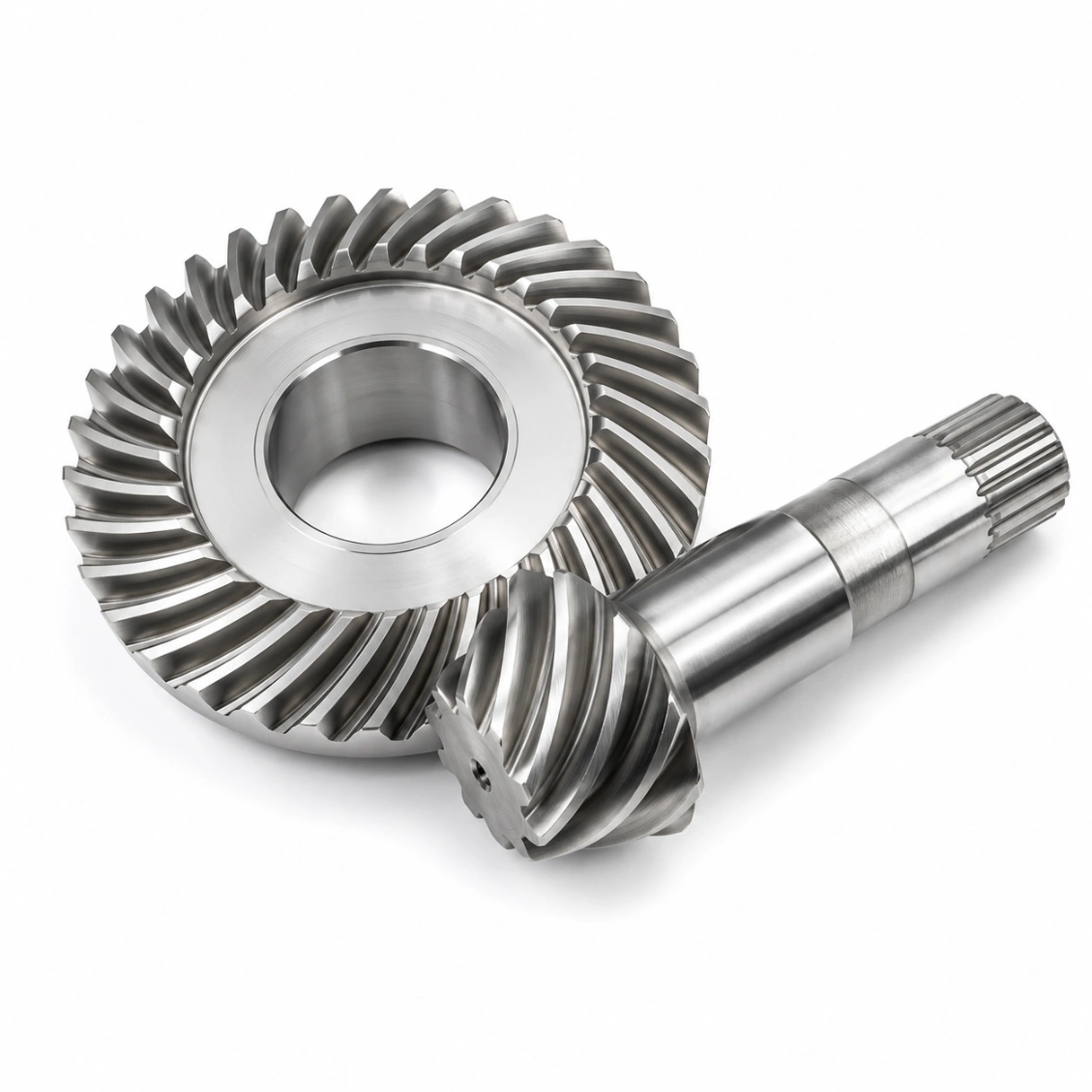
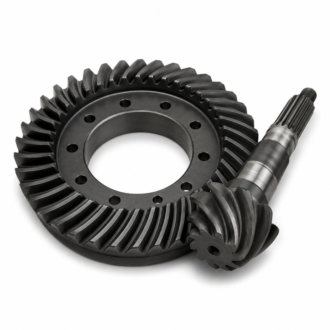
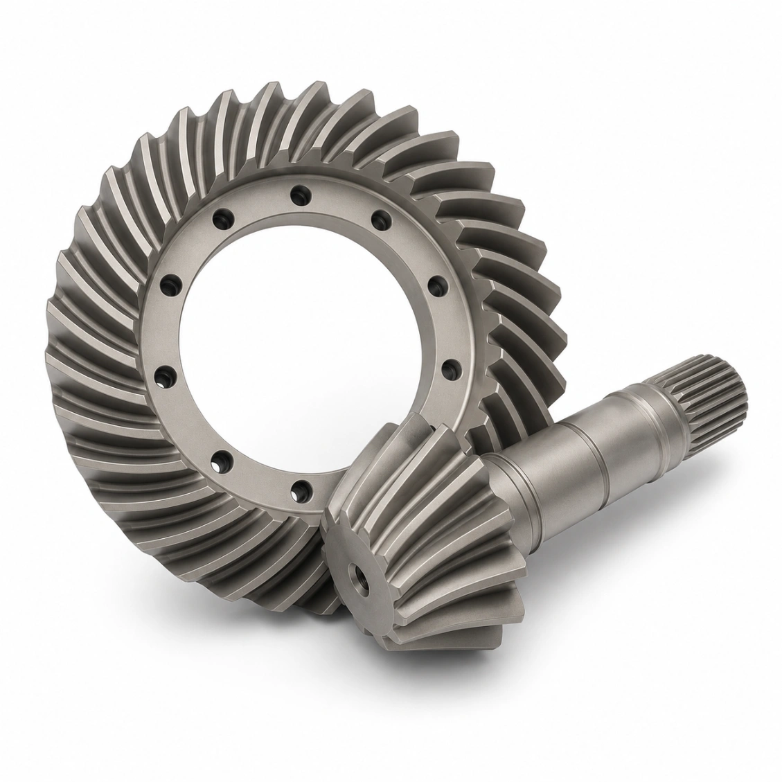
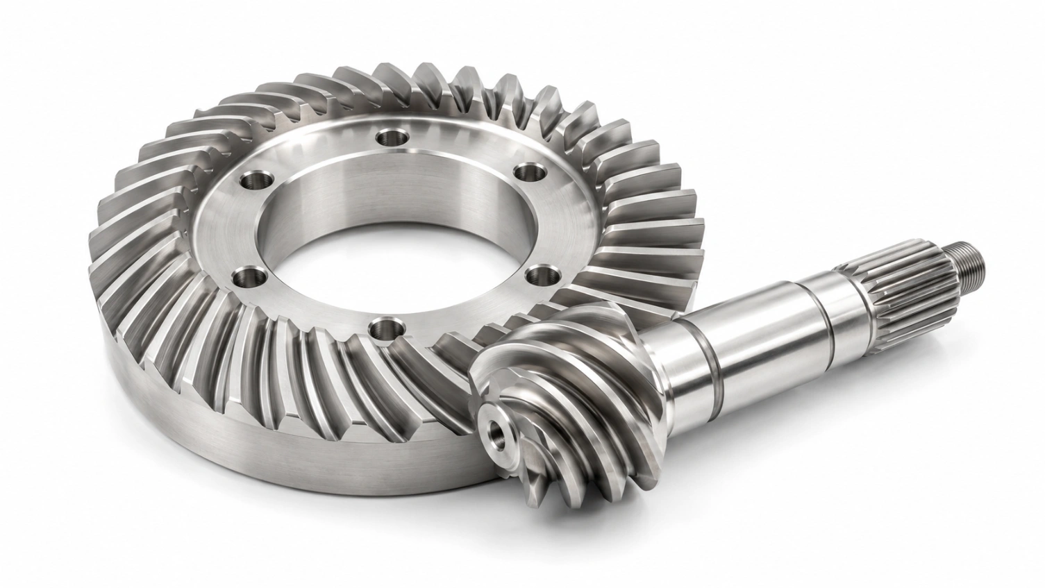
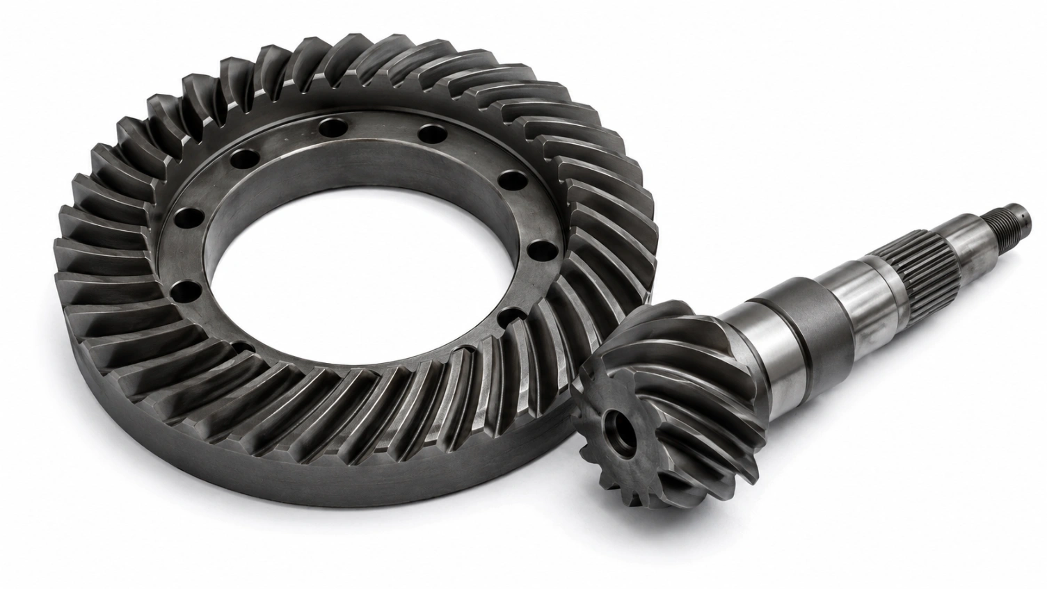
Engrenages coniques hélicoïdaux de haute précision selon les normes Gleason et DIN. Module 1–16, tout angle d'arbre, tout angle d'hélice — de la prototypie à la production de masse, chaque pièce entièrement inspectée au CMM avec vérification du motif de contact.
Quatre processus — de la production de roues dentées à face fraisée Gleason à des ensembles de précision ultra-lissés pour l'aérospatiale.
⚙️
Fraisage à face (Gleason)
Haute production
🔬
Rectification d'angle
Ultra-précision
🏭
Lapping (ensembles assortis)
Faible bruit / NVH
🔧
Fraisage CNC 5 axes
Prototype / angle personnalisé
Fraisage de face — Système Gleason
Les machines de fraisage de face CNC Gleason génèrent la géométrie dentaire à conicité duplex standard dans les différentiel automobiles et les engrenages coniques de transmission de puissance. Idéal pour la production en volume moyen à élevé d'ensembles de pignons et de couronnes assortis.
Gamme de module
1,5 – 16 mm
Diamètre de pas maximal.
600 mm
Angle de l'arbre
45° – 135° (standard 90°)
Classe de qualité
DIN 6–9 standard
Tolérance du profil de dent.
±0,012 mm
Quantité typique
50 – 20 000 pièces
Délai de livraison
10 – 18 jours
Matériaux
Acier, Al, Inox
Rectification d'engrenages coniques
Rectification CBN après coupe ou après trempe sur des rectifieuses de cône dédiées. Atteint une précision DIN 4–5 en dents et une finition de flanc Ra ≤ 0,4 µm pour les applications aéronautiques et d'instruments de précision.
Gamme de module
1 – 10 mm
Diamètre de pas maximal.
350 mm
Classe de qualité
DIN 4–6 précision
Tolérance du profil de dent.
±0,006 mm
Finition de surface Ra
0,2 – 0,6 µm
Traitement thermique après fabrication
Oui — rectification durcie
Délai de livraison
12 – 22 jours
Matériaux
20CrMnTi, 42CrMo4, M2 HSS
Polissage — Ensembles appariés
Le polissage des engrenages fait fonctionner le pignon et la roue dentée ensemble avec un composé abrasif pour développer un motif de contact optimal et minimiser le NVH. Les ensembles appariés sont marqués, emballés et livrés ensemble pour un montage direct.
Gamme de module
1,5 – 12 mm
Diamètre de pas maximal.
500 mm
Motif de contact
Selon le dessin du client
Réduction du bruit
3–8 dB par rapport à la coupe seule
Finition de surface Ra
0,3 – 0,8 µm
Marquage
Numéro de série de l'ensemble apparié
Délai de livraison
12 – 20 jours
Usage courant
Automobile, transmissions marines
Fraisage CNC 5 axes
Engrenages coniques hélicoïdaux personnalisés avec des angles d'arbre non standard, des flasques intégrés ou des géométries uniques usinées en une seule configuration à 5 axes. Idéal pour les prototypes et les designs spéciaux en faible volume.
Gamme de module
2 – 16 mm
Diamètre de pas maximal.
480 mm
Angle de l'arbre
Tout — entièrement programmable
Classe de qualité
DIN 7–9
Tolérance du profil de dent.
±0,018 mm
Quantité Minimum de Commande
1 pièce
Délai de fabrication (prototype)
7 – 12 jours
Matériaux
Tous métaux + plastiques techniques
Matériaux
Plus de 50 matériaux certifiés
Certificats de fabrication complets et analyse spectrale sur chaque lot.
Métaux
Plastiques d'ingénierie
Acier inox SUS316L
Applications de spirales coniques de qualité marine, agroalimentaire et médicale.
MaritimeNorme alimentaire
Acier allié 42CrMo4
Traitement thermique par trempe, excellente résistance à la fatigue et aux chocs pour les entraînements lourds.
RobusteIndustriel
Al 7075-T6
Résistance supérieure à celle du 6061, anodisable. Transmissions pour l'aérospatiale et les drones.
LégerAérospatiale
Laiton C36000
Usinage facile, faible bruit, idéal pour les instruments et les entraînements coniques légers.
Faible bruitInstruments
Acier 20CrMnTi
Trempé en bain, surface HRC 58–62, noyau résistant. Norme industrielle pour les engrenages coniques automobiles.
Charge élevéeTrempé
POM (Delrin)
Autolubrifiant, stable dimensionnellement. Entraînements coniques légers avec faible bruit.
Auto-lubrifiéFaible bruit
Nylon PA66-GF30
Renforcé de verre 30% pour une rigidité accrue. Réduction du fluage sous charge soutenue.
Haute résistanceLéger
PEEK
Résistant aux produits chimiques, supporte jusqu'à 260°C. Engrenages coniques de qualité médicale stérilisables.
Haute TempératureRésistance Chimique.
Études de cas
Projets réels, Résultats réels
Commandes sélectionnées illustrant notre gamme — de prototypes uniques à des séries de production de plus de 5 000 ensembles assortis.
Automobile
Ensemble de pignons de différentiel d'essieu arrière
Matériau
20CrMnTi
Processus
Gleason + Lap
Quantité
1500 ensembles
Délai de livraison
18 jours
✓ Motif de contact approuvé en 1 cycle · aucun retour sous garantie
Aérospatiale
Ensemble de pignons coniques hélicoïdaux pour boîte de vitesses UAV
Matériau
Ti-6Al-4V
Processus
5 axes + rectification
Quantité
40 ensembles
Grade
DIN 5
✓ Approuvé par FAI en premier cycle · rapport CMM complet joint
Maritime
Paire de pignons coniques de direction marine
Matériau
SUS316L
Processus
Fraise face + passivation
Quantité
120 ensembles
Délai de livraison
14 jours
✓ Certificats de conformité des matériaux DNV fournis · testé en brouillard salin 500 h
Comment ça fonctionne
De la dessin à votre porte
Téléchargez votre fichier CAD ou fiche récapitulative Gleason — nous gérons tout, de la conception pour la fabrication (DFM) à la validation du motif de contact et à l'expédition mondiale.
01
Télécharger CAO / Dessin
STEP, IGES, DXF, DWG, fiche récapitulative Gleason ou données dentaires PDF — tous formats acceptés.
02
Devis en 48 heures
Recommandation de processus, sélection des matériaux, analyse du ratio de contact, délai ferme avec ventilation des coûts.
03
Contrôle de l'usinage et du contact
Découpe de pignons CNC avec mesure en cours de processus Klingelnberg et vérification du motif de contact avant expédition.
04
Expédition dans le monde entier
Ensembles assortis emballés sous vide avec numéros de série, rapport d'inspection complet joint. DHL / FedEx / fret maritime.
Qualité
Engagement zéro défaut
Chaque engrenage conique spiral subit un protocole d'inspection en 4 étapes, y compris la vérification du motif de contact, avant de quitter nos installations.
Certifications & Équipements
✓
ISO 9001:2015
Système de gestion de la qualité — tous les processus certifiés
📐
Normes Gleason / DIN
Classes de tolérance DIN 3965 4–10, calcul de géométrie Gleason disponible
🔭
Testeur Klingelnberg + Gleason
Des testeurs d'engrenages coniques dédiés mesurent le motif de contact des dents, le voile et l'erreur d'espacement des dents
📄
Certification complète du matériau
Certificat de laminoir + analyse spectrale sur chaque lot de matériaux ; certificats tiers disponibles
Protocole d'inspection en 4 étapes
1
Contrôle des matériaux entrants
L'analyseur spectral vérifie la nuance d'alliage et le numéro de coulée avant le début de l'usinage.
2
Inspection du premier article
Mesure CMM complète du premier engrenage — toutes les dimensions critiques confirmées avant le début de la production en série.
3
Vérification du motif de contact
Le testeur Klingelnberg confirme l'emplacement et la forme du motif de contact des dents par rapport à la zone cible approuvée par le client.
4
Inspection finale de sortie
Visuel 100% + CMM par échantillonnage. Rapport de mesure complet et photographie du motif de contact expédiés avec chaque commande.
Avis
De confiance des ingénieurs du monde entier
★★★★★
"1 500 jeux d'engrenages coniques appariés pour notre chaîne de montage d'essieux arrière. Le motif de contact était parfait sur chaque jeu — a passé notre inspection entrante du premier coup sans aucune retouche. Cohérent d'un lot à l'autre."
TF
Thomas F.
Ingénieur en transmission · France
★★★★★
"Engrenages coniques spiraux en titane prototypes pour notre boîte de vitesses d'UAV arrivés en 9 jours. Le rapport CMM était complet. FAI approuvé au premier cycle et nous sommes maintenant en production série avec HXC."
LB
Lena B.
Ingénieure systèmes · France
★★★★★
"Engrenages coniques en acier inoxydable marin nécessitant des certificats de matériaux DNV. HXC a fourni une documentation complète et les engrenages ont passé notre test de brouillard salin sans aucun problème. Livraison exactement dans les délais."
PK
Piotr K.
Responsable des achats · France
FAQ
Foire aux questions
Tout ce que les ingénieurs et les acheteurs demandent sur les engrenages coniques hélicoïdaux — répondu par notre équipe de fabrication.
Un engrenage conique hélicoïdal est un engrenage conique dont les dents sont taillées le long d'une trajectoire courbe et oblique sur la face du cône de l'engrenage, par opposition aux dents radiales droites d'un engrenage conique droit. La dent courbe produit un engrènement progressif et chevauchant des dents plutôt qu'un contact linéaire abrupt, ce qui confère aux engrenages coniques hélicoïdaux leurs avantages caractéristiques : capacité de charge plus élevée, bruit réduit et fonctionnement plus doux. Ils sont utilisés partout où la puissance doit être transmise entre des arbres sécants — presque toujours à 90°, bien que d'autres angles soient possibles.
Les deux types transmettent la puissance entre des arbres sécants et partagent la même géométrie conique. La différence réside dans la forme des dents : les engrenages coniques droits ont des dents qui pointent directement vers l'apex du cône — simples à fabriquer mais plus bruyants et de moindre capacité de charge. Les engrenages coniques hélicoïdaux ont des dents courbes et obliques qui s'engrènent progressivement, leur conférant une capacité de charge 20 à 40 % plus élevée pour la même taille, un bruit beaucoup plus faible (typiquement 10 à 15 dB de moins) et une capacité de vitesse de ligne de pas plus élevée. Le compromis est une complexité de fabrication accrue et la nécessité d'un roulement de butée pour supporter la charge axiale générée par l'angle d'hélice.
L'angle d'hélice (β) est l'angle entre la trace de la dent au cône de pas et un générateur du cône de pas. Il détermine le degré d'obliquité des dents. L'angle d'hélice standard est de\n 35° dans les engrenages du système Gleason — une valeur qui équilibre la capacité de charge, la poussée axiale et la\n fabricabilité. Des angles d'hélice plus élevés augmentent le rapport de contact (fonctionnement plus doux) mais augmentent également la poussée axiale. Les angles de 25° à 45° sont courants ; le système Gleason utilise un angle d'hélice moyen\n de 35° par défaut pour la plupart des conceptions automobiles et industrielles.
"\ procédé de fraisage de face qui génère une profondeur de dent conique\n (Duplex Taper), avec la conicité des dents adaptée entre la couronne et le pignon. Le système Gleason\n définit tous les paramètres : rayon de fraise, angle d'hélice, angle de pression, type de conicité des dents et les\n méthodes de calcul du contact des dents. Un système alternatif est Klingelnberg\n (Palloid), qui utilise un procédé de taillage par vis sans fin continu produisant une profondeur de dent uniforme.
Les deux se ressemblent mais diffèrent par la géométrie de l'arbre : engrenages coniques hélicoïdaux ont des axes sécants — l'axe du pignon et l'axe de la couronne se croisent en un point. Engrenages hypoidaux ont des axes décalés\n (non sécants, non parallèles) — l'axe du pignon est décalé en dessous (ou au-dessus) de l'axe de la couronne.\n Les engrenages hypoïdes permettent au pignon d'être plus grand et plus résistant pour la même taille de couronne, permettent à l'arbre de transmission d'être plus bas (utilisé dans la plupart des essieux arrière automobiles pour une hauteur de plancher plus faible), et peuvent supporter plus de charge, mais sont moins efficaces en raison de l'action de glissement et nécessitent une huile pour engrenages extrême pression (EP).\n Les engrenages coniques hélicoïdaux sont plus simples, plus efficaces et préférés lorsque le décalage d'axe n'est pas nécessaire.
Les engrenages coniques hélicoïdaux sont la solution standard partout où la puissance doit changer de direction entre\n des arbres sécants: automobile différentiels, boîtiers de transfert et prises de force ;
aérospatial boîtes de vitesses accessoires et entraînements d'actionneurs d'hélicoptères ; marine
systèmes de direction et entraînements de propulseurs ; industrie lourde entraînements à angle droit pour mélangeurs,\n convoyeurs et fraiseuses ; startup en robotique articulations de poignet et systèmes panoramiques/d'inclinaison de caméra ; agriculture boîtes de vitesses de prise de force. Toute application combinant un couple élevé,\n une vitesse modérée à élevée, et une configuration à arbre croisé est un candidat naturel.
Principaux avantages par rapport aux engrenages coniques droits : capacité de charge plus élevée (20–40% de plus pour la\n même taille — le contact de dents superposé répartit mieux la charge) ; bruit et\n vibration plus faibles (engagement progressif, généralement 10–15 dB plus silencieux) ; capacité de vitesse\n du cercle primitif plus élevée (les engrenages coniques droits sont limités à environ 5 m/s ; les engrenages coniques hélicoïdaux\n fonctionnent en douceur au-dessus de 40 m/s) ; transmission de couple plus fluide — pas de chargement d'impact ; et durée de vie plus longue.
Quels sont les inconvénients des engrenages coniques hélicoïdaux ? Les principales limitations sont : complexité et coût de fabrication plus élevés; — la coupe nécessite\n des machines spécialisées Gleason ou Klingelnberg, et non des machines à engrener standard ;
charge de poussée axiale; sensibilité du motif de contact — la distance de montage précise
et la précharge du palier sont critiques, des déviations modifient le motif de contact et réduisent la durée de vie de l'engrenage ;
la main de la spirale importe — les pignons à main gauche et à main droite ne sont pas interchangeables ;
et lapping est souvent nécessaire pour les applications automobiles afin d'optimiser le motif de contact,
ajoutant une étape de processus.
Le motif de contact est la zone de la face d'une dent d'engrenage conique qui transmet réellement la charge lors
de l'engrènement. Il est visualisé en appliquant un composé de marquage fin sur les dents et en faisant rouler la paire d'engrenages
sous une charge légère — le composé se transfère sur la dent en face, révélant la zone de contact.
Un motif de contact idéal est centré sur la face de la dent, légèrement biaisé vers l'extrémité (petite
extrémité) en l'absence de charge, et se déplace vers le talon (grande extrémité) sous charge maximale. Les motifs qui sont
trop proches du talon ou de l'extrémité concentrent le stress et causent une usure prématurée ou une fatigue. La vérification du motif de contact
est une étape obligatoire lors de l'inspection sortante de HXC pour toutes les commandes d'engrenages coniques.
La main de la spirale décrit la direction dans laquelle les dents courbent sur la face du cône. Vu depuis l'arrière de l'engrenage, droite (RH) les dents suivent une courbe dans le sens horaire, en s’éloignant de l’apex ;
main gauche (MG) les dents suivent une courbe dans le sens antihoraire. Un pignon à main droite s’engrène toujours avec une
roue dentée à anneau à main gauche et vice versa — ils ne sont pas interchangeables. La direction de la spirale
détermine également la direction de la force de poussée axiale : sous charge motrice, un pignon à main droite
génère une poussée éloignée de l’apex. Cela doit être spécifié sur le dessin et adapté à la disposition des roulements.
Les machines HXC fabriquent les deux mains sur commande ; veuillez préciser sur votre dessin ou demande.
Les angles de pression les plus courants dans les engrenages coniques à spirale Gleason sont 20° et 22,5°. Un
angle de pression de 20° est standard pour la plupart des engrenages industriels et automobiles. Un angle de
pression de 22,5° augmente la résistance à la racine des dents et réduit la tendance à l’incurvation de la racine
des dents à faible nombre de dents. 20° est la valeur par défaut chez HXC; 22,5° et 25° sont disponibles sur demande. Des angles de pression plus élevés
augmentent la force normale sur la dent (et donc les charges sur les roulements) mais permettent
des dents plus courtes et plus solides. L’angle de pression doit être identique entre le pignon et la roue dentée — il ne peut pas être
mélangé.
Les engrenages coniques à spirale peuvent être produits dans pratiquement tous les rapports, mais les rapports en une seule étape
pratiques varient de 1:1 à environ 8:1. Des rapports supérieurs à 8:1 sont possibles mais le pignon devient
très petit avec peu de dents, ce qui le rend structurellement faible ; une configuration à deux étapes est généralement préférée
au-delà de 8:1. La gamme la plus courante est 1,5:1 à 5:1. À un rapport de 1:1 (engrenages à crémaillère), le
ensemble est symétrique et les deux engrenages sont identiques — très courant dans les entraînements de bras d’instruments et de robots. HXC
peut calculer le nombre optimal de dents pour tout rapport requis ; indiquez simplement votre rapport et la vitesse de l’arbre dans la demande.
Un engrenage à crémaillère est simplement un engrenage conique avec un rapport de 1:1 — les deux engrenages ont la même taille
et le même nombre de dents. Ils sont utilisés pour changer la direction de l’arbre de 90° sans changer
la vitesse. Étant donné que les deux engrenages sont identiques, un ensemble d’engrenages à crémaillère est la conception de conique la plus économique (une référence SKU
au lieu de deux). Ils peuvent être droits, à spirale ou à spirale zéro. Les engrenages coniques à spirale offrent les
mêmes avantages en termes de bruit et de capacité de charge que les autres engrenages coniques à spirale et sont courants dans les entraînements à angle droit pour instrumentation, robotique et boîtiers d’engrenages industriels compacts.
Les engrenages coniques Zerol sont un cas particulier : ils ont des dents courbes comme les engrenages coniques hélicoïdaux mais un
angle de spirale moyen nul — les dents se courbent sur la face mais sont tangentes au générateur du cône primitif au point médian. Cela signifie que les engrenages coniques Zerol ont aucune charge de poussée axiale nette (un avantage par rapport aux engrenages coniques hélicoïdaux), tout en conservant l'engagement progressif des dents et le bruit plus faible des dents courbes (un avantage par rapport aux engrenages droits). Le compromis est une capacité de charge plus faible que celle des engrenages coniques hélicoïdaux de même taille, car le rapport de contact est plus faible. Les engrenages coniques Zerol sont principalement utilisés dans les accessoires d'avions et les entraînements d'instruments où l'élimination de la poussée axiale est plus importante que la maximisation de la capacité de charge.
Pour une durée de vie maximale en fatigue de contact et de flexion — entraînements automobiles et industriels —
acier cémenté 20CrMnTi (carburé à HRC 58–62) et 18CrNiMo7-6
sont les choix standards de l'industrie, tous deux trempés puis rectifiés selon la norme DIN 5–6. Pour les entraînements à angle droit industriels lourds, 42CrMo4 trempé à HRC 50–55 est préféré.\nPour les environnements marins et corrosifs, Inox SUS316L avec passivation. Pour\nles applications aérospatiales où le poids est critique, Ti-6Al-4V or Al 7075-T6. Pour les entraînements à angle droit à faible charge et faible bruit, laiton C36000 or POM associé à un pignon d'entraînement en acier réduit considérablement le bruit.
Fournissez autant d'informations que possible parmi les suivantes : module (ou pas diamétral),
nombre de dents du pignon et de la roue (ou rapport requis), angle de l'arbre (habituellement 90°), main de la spirale (pignon LH ou RH), angle de pression (20° si non précisé), largeur de face, distance de montage et angle arrière, classe de qualité (classe DIN), matériau, traitement thermique et dureté, exigence de finition de surface, et
quantité. Une fiche récapitulative Gleason ou un fichier STEP avec les données des dents est idéal. Si vous ne disposez que d’un rapport de ratio et d’une exigence de puissance, nos ingénieurs peuvent calculer la géométrie complète — il suffit de fournir la vitesse de l’arbre, le couple et les contraintes d’enveloppe.
Le jeu dans les engrenages coniques est le dégagement entre les flancs des dents non motrices d’une paire d’engrenages en prise,
mesuré au cercle de pitch dans le plan normal. Il est ajusté lors de l’assemblage en calant
l’engrenage de pignon ou la roue dentée par l’axe, non usiné dans chaque engrenage — c’est pourquoi le jeu monté plutôt que les tolérances individuelles des engrenages est la spécification pertinente. Les valeurs typiques de jeu pour un ensemble d’engrenages coniques automobiles à module 3 sont 0,08–0,18 mm; pour un ensemble d’instruments à module
1,5 de précision, 0,02–0,06 mm. La norme DIN 3967 définit les classes de tolérance de jeu. Pour
les ensembles assortis, HXC peut vérifier le jeu assemblé sur notre testeur d’engrenages et fournir une recommandation d’épaisseur de cales cible.
Obtenir un devis
Envoyez votre dessin. Obtenez un devis.
Chaque demande comprend une revue DFM — faisabilité des tolérances, confirmation du matériau et approche du processus avant le début de la production. MOQ 1 pièce.
24hr
Réponse au devis
Quantité Minimum de Commande 1
Prototypes OK
ISO
9001:2015
📐
Revue DFM sur chaque demande
Faisabilité des tolérances, stratégie de fixation et confirmation des matériaux. Retour spécifique et exploitable — pas de refus générique.
🎯
Inspection du premier article — Standard
Rapport FAI sur chaque nouvelle série. Certificats de matériaux et de traitement de surface inclus avec chaque expédition.
🔄
Même processus : Prototype à Production
Le plan de processus de votre prototype s'applique aux lots de production. Pas de requalification lors de la montée en gamme.
⚙
Usinage CNC 3 / 4 / 5 axes + tournage
Pièces structurelles complexes, arbres, boîtiers et composants de transmission. Métaux et plastiques d'ingénierie.
ISO 9001:2015Fraisage 3/4/5 axesTournage CNCInspection CMMLivraison mondiale