
What Is Plasma Cutting? Understanding the Fourth State of Matter
When we talk about shifting from traditional metalworking to high-efficiency fabrication, we have to look at the science powering the modern workshop. To understand how a thermal cutting process slices through thick steel like butter, we first need to break down the physics of plasma itself.
What is Plasma?
Most of us are familiar with the three basic states of matter: solids, liquids, and gases. Plasma is the fourth state. When you introduce extreme energy—like a high-voltage constricted electrical arc—to a gas, the atoms split apart. This separation creates a superheated, highly charged mix of free electrons and ions. In our shop, we harness this energetic state to create a focused ionized gas jet that melts and blasts away metal instantly.
Electrical Conductivity and Quasi-Neutrality
Because plasma is packed with free-moving electrons, it behaves completely differently than standard gas.
- High Electrical Conductivity: Plasma conducts electricity with minimal resistance. This allows us to maintain a continuous, stable transferred arc mode between the plasma torch and the workpiece.
- Quasi-Neutrality: On a macroscopic level, the positive ions and negative electrons balance each other out. This collective equilibrium keeps the high-velocity plasma stream tightly focused and controllable, ensuring predictable energy delivery.
Energy Transfer Dynamics
The core efficiency of plasma arc cutting (PAC) relies on rapid energy conversion. The moment the plasma stream hits the target, it transfers massive thermal and kinetic energy simultaneously.
| Energy Type | Role in the Cutting Process |
|---|---|
| Thermal Energy | Instantly liquefies the conductive metals at temperatures exceeding 20,000°C. |
| Kinetic Energy | Uses high-velocity gas pressure to blow the molten metal away, minimizing dross formation. |
By forcing compressed gas through a restrictive nozzle, we focus this energy into a tight, high-density beam. This localized heat minimizes the Heat-Affected Zone (HAZ), preventing material warping and delivering a cleaner, sharper cut.
The Plasma Cutting Working Principle (Step-by-Step)
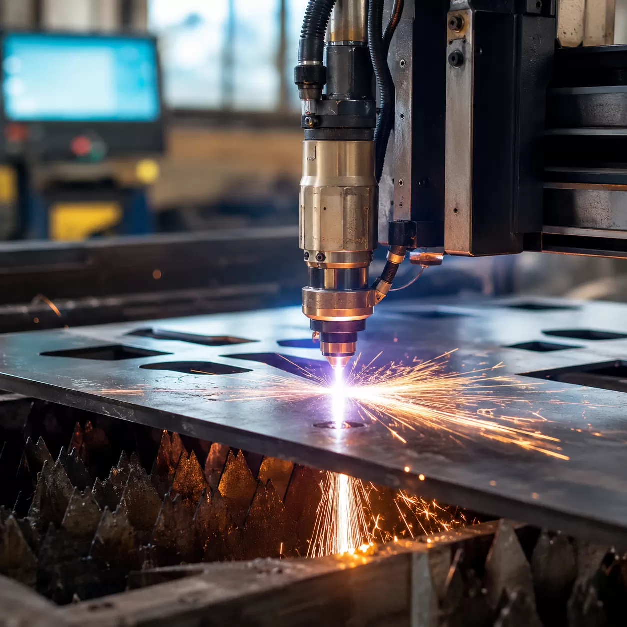
Understanding how a plasma torch slices through heavy metal comes down to a highly controlled, four-stage thermal cutting process. Here is exactly how we harness an ionized gas jet to achieve clean, precision cuts.
Phase 1: Pilot Arc Ignition
The process begins when you trigger the torch. A high-frequency, high-voltage electrical circuit creates a small, high-intensity spark inside the torch body. This spark ignites a low-powered pilot arc between the internal electrode and the torch nozzle. At this stage, the arc is contained entirely within the torch head and does not yet touch the metal plate.
Phase 2: Gas Constriction and Ionization
Next, high-pressure gas—such as compressed air, nitrogen, or argon—is forced through a narrow nozzle orifice, directly surrounding the pilot arc. This extreme constriction forces the gas to move at near-sonic speeds while squeezing the electrical energy into a tight column. The intense heat of the arc strips electrons from the gas atoms, transforming the gas into a superheated, highly conductive plasma stream.
Phase 3: Arc Transfer to the Workpiece
Once the torch gets close enough to the target metal, the path of least resistance changes. The main power supply shifts the electrical ground from the nozzle directly to the workpiece. The plasma arc instantly jumps, establishing a transferred arc mode. This creates a continuous, heavily constricted electrical arc that concentrates thousands of degrees of heat onto a highly localized area of the metal.
For large-scale structural fabrications, this massive energy delivery easily penetrates thick components, a process crucial when manufacturing heavy-duty alloy steel power transmission parts or massive machine frameworks that require perfectly square edges.
Phase 4: Material Displacement
As the intense thermal energy melts the metal instantly, the high-velocity plasma stream acts as a mechanical broom. The kinetic energy of the high-speed gas blows the molten metal straight through the bottom of the cut. This continuous melting and blowing action creates the kerf width (the slot left behind by the cut) and leaves behind a clean, separated edge as the torch moves along its path.
Core Types of Plasma Cutting Systems
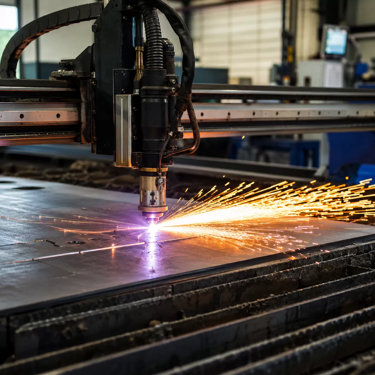
Choosing the right plasma arc cutting (PAC) setup comes down to your material thickness, production volume, and the level of precision your shop demands. We break down the primary configurations used across the industry today.
Conventional Air Plasma Cutting
This is the standard entry point for most shops. Conventional systems rely on a single gas—typically compressed air plasma—to both ignite the arc and cool the torch.
- Best For: General maintenance, light fabrication, and thin gauge sheet metal.
- The Upside: Highly economical and simple to operate since you don’t need expensive specialty gases.
- The Downside: Cut quality can suffer on thicker plates, often leaving more dross and a wider kerf width.
Dual-Flow & Water Shield Systems
For high-volume operations handling demanding materials, dual-flow systems introduce a secondary shield gas (like oxygen, nitrogen, or argon-hydrogen) around the central plasma stream. This secondary gas constricts the arc further, concentrating the thermal energy.
Some advanced setups swap the shield gas for water. Utilizing a water shield or cutting over a water table drastically reduces smoke, dampens noise, and narrows the Heat-Affected Zone (HAZ) to prevent material warping. This precision setup is ideal when prep work requires clean, weld-ready edges on nickel-based alloy CNC parts and heavy structural plates.
Handheld vs. Mechanized Systems
The choice between a manual torch and an automated system depends entirely on your production workflow.
| Feature | Handheld Plasma Systems | Mechanized Plasma Systems |
|---|---|---|
| Operation | Manual, operator-guided torch. | Mounted to a CNC plasma table or robotic arm. |
| Best Used For | Scrap yards, field repairs, and quick, non-linear cuts. | High-volume manufacturing and repeatable geometric parts. |
| Precision | Variable; highly dependent on operator hand steadiness. | Exceptional; precise tracking with minimal kerf angularity. |
| Consumable Life | Shorter life due to inconsistent standoff distances. | Maximized via automated torch height control systems. |
Process Parameters That Optimize Plasma Cutting Quality

Achieving a clean, precise edge with plasma arc cutting (PAC) requires dialing in specific system variables. If these parameters are out of balance, you risk dealing with excessive dross formation, wide kerf width, or a massive heat-affected zone (HAZ).
Here is how to set up a system for the best results:
- Amperage (Current Intensity): The thickness of the material dictates your amperage. Higher current delivers the thermal power needed for thick plates, while lower amperage prevents melting or warping on thin sheet metal.
- Travel Speed (Cutting Velocity): Moving too fast causes an incomplete cut and excessive top dross. Moving too slow pools intense heat in one spot, widening the kerf and creating hard, heavy bottom dross.
- Standoff Distance: The gap between the torch tip and the workpiece maintains arc stability. A consistent standoff prevents premature wear on your plasma torch consumables and ensures a square, clean edge.
- Gas Selection by Material Type: The choice of gas directly affects the plasma chemistry. While compressed air plasma works perfectly for everyday mild steel, specialized applications require different gases to prevent oxidation and maintain material integrity.
The quick-reference chart below breaks down the optimal gas choices across common conductive metals, which is especially critical when preparing blanks for high-precision carbon steel CNC machining or complex sheet fabrication.
| Material Type | Primary Plasma Gas | Shield Gas | Impact on Cut Quality |
|---|---|---|---|
| Carbon/Mild Steel | Compressed Air / Oxygen (O2) | Compressed Air / Nitrogen (N2) | Offers the fastest cutting speeds and cleanest edges on standard steels. |
| Stainless Steel | Nitrogen (N2) / F5 (95% N2, 5% H2) | Nitrogen (N2) / Air | Prevents heavy oxidation and maintains excellent corrosion resistance. |
| Aluminum | Nitrogen (N2) / Argon-Hydrogen mix | Compressed Air / Nitrogen (N2) | Delivers a smooth, square edge on highly reflective, non-ferrous metals. |
Major Advantages of Plasma Cutting
When we look at the demands of modern American fabrication shops, the thermal cutting process stands out for its sheer utility. Plasma cutting offers a distinct set of operational benefits that directly impact shop throughput and the bottom line.
Versatility Across Conductive Metals
Unlike oxy-fuel, which relies on chemical oxidation and only works on ferrous metals, a plasma arc cutting (PAC) system cuts through any material that conducts electricity. We regularly process heavy-duty stainless steel, aluminum, brass, copper, and cast iron. This versatility makes it indispensable for shops that work heavily with specialized nickel-based alloys cnc machining or structural carbon steels.
Superior Operational Speed
Time is money in any production environment. Plasma cutting delivers blistering speeds, especially on thin to medium metal thicknesses.
- Zero Preheat Time: Unlike oxy-fuel, which requires heating the metal to its ignition temperature, the high-velocity plasma stream cuts instantly upon arc transfer.
- Rapid Linear Travel: On gauge materials, plasma cuts up to one-fourth of the time it takes conventional methods, significantly boosting daily output.
Unmatched Cost Efficiency
Operational costs drop dramatically when switching to plasma. The primary fuel source is compressed air plasma, which eliminates the need for expensive, volatile bottled gases like acetylene.
| Cost Factor | Plasma Cutting | Oxy-Fuel Cutting |
|---|---|---|
| Primary Fuel Cost | Low (Compressed Air / Electricity) | High (Oxygen / Acetylene Gas) |
| Consumable Lifespan | Long-lasting modern nozzles & electrodes | Frequent tip cleaning and replacement |
| Secondary Labor | Minimal (Clean cuts, low dross) | High (Requires grinding/slag removal) |
Complex Geometric Freedom
The constricted electrical arc creates a highly localized heat source, resulting in a narrow kerf width. This tight focus allows us to execute intricate designs, sharp angles, and tight radii without warping the surrounding material. It provides the freedom to cut complex bracketry, custom signage, and detailed industrial parts with extreme precision.
Integration with CNC Automation
When you mount a plasma torch to a CNC plasma table, you unlock industrial-scale repeatability. Automated systems precisely control travel speed, torch height, and pierce delays. This integration ensures that the first part matches the ten-thousandth part perfectly, seamlessly feeding high-quality blanks into subsequent manufacturing stages or industrial automation components assembly lines.
Key Material Challenges and Mitigation Strategies
While plasma arc cutting (PAC) is a powerhouse for slicing through conductive metals, it isn’t without its quirks. To get those flawless, factory-grade cuts, we have to actively manage how the thermal cutting process impacts the metal.
Here is how we tackle the three biggest challenges on the shop floor:
Managing the Heat-Affected Zone (HAZ)
Because plasma cutting relies on an intense, high-velocity plasma stream, extreme heat transfers into the surrounding metal. This creates a Heat-Affected Zone (HAZ)—an area near the cut edge where the metal’s microstructure alters, sometimes leading to hardening or warping.
- The Fix: Increase your travel speed. Moving the plasma torch faster reduces the dwell time on the metal, keeping the HAZ as narrow as possible. Proper gas selection also helps concentrate the arc, minimizing unnecessary heat bleed.
Eliminating Dross Formation
Dross is the unwanted, re-solidified metal dross that sticks to the bottom of your workpiece. It is a common headache that ruins edge quality and forces you to waste time on secondary grinding.
- High-Speed Dross: Occurs when the torch moves too fast, preventing the ionized gas jet from fully blowing the molten metal out of the kerf width.
- Low-Speed Dross: Occurs when the torch moves too slow, causing the arc to widen and melt excess material.
- The Fix: Dial in your amperage and cutting velocity to match your material thickness. Keeping your plasma torch consumables fresh ensures a clean, consistent blow-out.
Minimizing Kerf Angularity
A perfect cut should be completely perpendicular, but the nature of a constricted electrical arc means the torch naturally creates a slight bevel or V-shape in the cut path.
- The Fix: Keep a close eye on your torch height control and standoff distance. If the torch is too high or too low, the angle worsens. For automated setups on a CNC plasma table, ensuring precision components like high-performance bevel gears are properly calibrated keeps the motion smooth and cuts square.
| Challenge | Primary Cause | Best Mitigation Strategy |
|---|---|---|
| HAZ Expansion | Excessive heat dwell time | Increase travel speed & optimize gas selection |
| Dross Formation | Incorrect speed or worn nozzles | Tune amperage & replace consumables |
| Kerf Angularity | Arc deviation / incorrect height | Adjust standoff distance & check machine alignment |
Industrial Applications of Plasma Cutting
Plasma cutting is a staple across major United States industrial sectors. Its ability to slice through conductive metals with speed and precision makes it indispensable for heavy-duty fabrication, routine maintenance, and large-scale salvage operations.
Heavy Manufacturing and Bridge Construction
In heavy manufacturing, efficiency and structural integrity are non-negotiable. Massive steel beams, thick plates, and structural components require clean cuts to ensure precise fitment and welding safety.
- Structural Steel Fabrication: Heavy machinery builders rely on a CNC plasma table to automate high-volume cutting with tight tolerances.
- Bridge Infrastructure: Creating gusset plates, stiffeners, and custom brackets requires a reliable thermal cutting process that minimizes material distortion.
- Custom Component Production: For complex machinery housings, heavy manufacturers integrate advanced stainless steel CNC machining alongside plasma cutting to achieve perfectly finished parts ready for assembly.
Automotive Fabrication and Repair
From custom hot rod shops to commercial fleet maintenance facilities, plasma arc cutting (PAC) keeps the automotive industry moving. It provides the agility needed to work on thin sheet metal and thick frame rails alike.
- Chassis Modification: Fabricators use localized compressed air plasma torches to slice through hardened frame sections without warping the surrounding metal.
- Exhaust and Bracket Work: Quickly removing rusted bolts, old exhaust pipes, and custom-shaping mounting brackets.
- Collision Repair: Sectioning damaged body panels rapidly, leaving a minimal Heat-Affected Zone (HAZ) that reduces the amount of grinding needed before welding.
Industrial Shipyards and Salvage Operations
Shipbuilding and demolition demand tools that can handle extreme material thicknesses and harsh environments. The high-velocity plasma stream excels where traditional oxy-fuel torches struggle, especially on non-ferrous metals.
- Hulking Hull Fabrication: Slicing through massive marine-grade steel and aluminum plates to build commercial vessels.
- Decommissioning and Salvage: Handheld plasma systems allow operators to quickly dismantle old ships, trains, and industrial structures.
- Stack Cutting: Plasma torches can cut through multiple layers of stacked metal sheets simultaneously, drastically reducing processing time in salvage yards.