
Sharp internal corners may look clean in CAD, but they can become crack starters, flow restrictions, sink-mark sources, and tooling cost drivers in injection molded parts.
The design goal is not to round everything blindly. The goal is to select a radius-to-thickness ratio that protects strength, maintains uniform wall thickness, supports polymer flow, and still preserves the intended industrial design.
High notch sensitivity, difficult flow, tooling wear risk.
Better than sharp, but still risky for brittle or filled resins.
Good starting point for many structural corners.
Outer radius follows inner radius plus wall thickness.
Are you tired of seeing apparently flawless CAD models crack near internal edges during testing, or receiving avoidable tooling-cost warnings during mold quotation? In many cases, the hidden culprit is the 90-degree corner.
In injection molding, sharp corners raise local stress, disturb the melt flow path, create cooling imbalance, and force fragile steel details into the mold. HXCNC reviews these risks through Design for Manufacturability, polymer behavior, and precision tooling constraints.
Why Sharp Corners Damage Injection Molded Parts
Sharp corners create structural, rheological, thermal, and tooling problems at the same time. A corner that is acceptable in a rendering can still fail in molding because molten plastic must flow, cool, shrink, and eject from a steel cavity.
Stress Concentration and the Notch Effect
The primary structural concern is the notch effect. When a load passes through a part, stress does not distribute evenly through a sharp inside corner. It concentrates at the smallest radius, where cracks can initiate.
- Stress concentration factor: A sharp geometry can multiply local stress, but the exact value depends on load case, part geometry, wall thickness, material, fiber orientation, and radius.
- Failure risk: Brittle, filled, or highly stressed plastics are especially vulnerable because they have less ability to yield and redistribute load around a notch.
Melt Flow Resistance
Molten polymer flows most predictably through smooth transitions. A sharp turn interrupts the melt front, increases shear, and can create a local pressure drop. If the material slows and cools too early, short shots, weld weakness, voids, gloss changes, or surface marks can appear downstream.
Residual Stress, Warpage, and Cracking
| Problem | Corner-Related Mechanism | Engineering Outcome |
|---|---|---|
| Differential cooling | Nonuniform wall thickness near the corner creates different cooling rates. | Warpage, sink, voids, and dimensional drift. |
| Molded-in stress | Polymer chains freeze under orientation and packing imbalance. | Stress whitening, delayed cracking, or reduced impact strength. |
| Ejection damage | Shrinkage grips sharp core features and increases friction. | Sticking, ejector marks, cracking, or deformation. |
Tooling Limitations and Mold Wear
A sharp plastic inside corner requires a sharp steel outside edge on the mold. That edge is difficult to machine, polish, cool, protect, and maintain. High-pressure polymer flow, fillers, glass fiber, and repeated thermal cycling can wear down the steel feature and eventually create flash or dimensional change.
Precision mold components often require careful material and process planning, including tool and mold steel selection and high-accuracy CNC milling.
Applying the Radius-to-Thickness Ratio

The radius-to-thickness ratio, usually written as R/T, compares the inside corner radius to the nominal wall thickness. It is one of the fastest ways to judge whether a molded corner is structurally and rheologically reasonable.
Inside Radius Starting Point
For many injection molded parts, an inside radius around 0.5T to 0.6T is a strong starting point for load-bearing corners. It reduces notch severity and supports smoother melt flow without creating an excessive thick zone.
Use this as a design starting point, not a universal law. Cosmetic covers, snap features, living-hinge areas, glass-filled materials, sealing features, and precision assemblies may require a different radius after simulation, prototype testing, or mold-flow review.
Radius and Stress Concentration
| Inside Radius Relative to Wall | Typical Trend | Risk Level |
|---|---|---|
| Sharp or near-zero radius | Highest local stress concentration and poorest flow transition. | Critical for brittle, filled, or impact-loaded parts. |
| ~0.2T | Noticeable improvement but still sensitive to material and load direction. | Moderate; validate if functional load is present. |
| ~0.5T to 0.6T | Substantially smoother stress and flow transition. | Good general target for many structural corners. |
| Very large radius | May improve stress flow but can affect packaging, mating geometry, and appearance. | Review against assembly and exterior design intent. |
The Mirror Principle for External Corners
Uniform Wall Corner
R_outer = R_inner + TWhen the outside radius follows the inside radius plus wall thickness, the corner maintains a more uniform section and cools more predictably.
Thick Corner Mass
Outer edge left sharpIf only the inside radius is added, the outside corner can become a thick mass that cools slowly and creates sink, voiding, or warpage.
The mirror principle is especially useful for enclosures, covers, and ribs with visible exterior geometry. HXCNC’s precision enclosures and housings work often involves this same balance between external appearance and manufacturable wall sections.
Material Selection and Polymer Notch Sensitivity

Material behavior determines how aggressively a corner radius must be managed. The same geometry may survive in a ductile polypropylene part and crack quickly in a glass-filled nylon or PMMA component.
Amorphous vs. Semi-Crystalline Polymers
- Amorphous polymers: PC, PMMA, and some ABS grades can be notch-sensitive. Their failure behavior depends heavily on stress, environment, impact rate, and molded-in orientation.
- Semi-crystalline polymers: PP, PE, POM, and PA can be more forgiving in some conditions because they may yield locally, but crystallinity, moisture, fiber reinforcement, and temperature change the result.
- Filled and reinforced polymers: Glass fiber increases stiffness but can raise notch sensitivity and create orientation-driven strength differences near gates and corners.
| Polymer Family | Corner Sensitivity | DFM Implication | Examples |
|---|---|---|---|
| Amorphous | Often moderate to high | Use generous radii and avoid high residual stress. | PC, PMMA, ABS |
| Semi-crystalline | Variable, often more forgiving | Still control radius, shrinkage, and warpage. | PP, PE, POM, PA |
| Glass-filled | High when loaded across fiber-sensitive notches | Increase radii and review fiber orientation. | GF nylon, GF PBT, GF PC |
High-Risk vs. Forgiving Materials
High-risk materials include brittle, filled, highly loaded, chemically exposed, or transparent polymers where stress whitening and crack initiation are unacceptable. More forgiving materials may tolerate smaller radii, but sharp corners can still create flow marks, sink, sticking, or tooling wear.
Material selection should be reviewed together with the full material strategy. Related machining work for plastic validation parts may include ABS, PC, and PMMA CNC parts or nylon PA components.
DFM warning: Draft, radius, shrinkage, and ejection cannot be separated. Stiff or filled plastics may grip cores aggressively during cooling, so corner radii should be reviewed with draft angle and ejector layout.
From CAD Screen to Mold Tooling Room
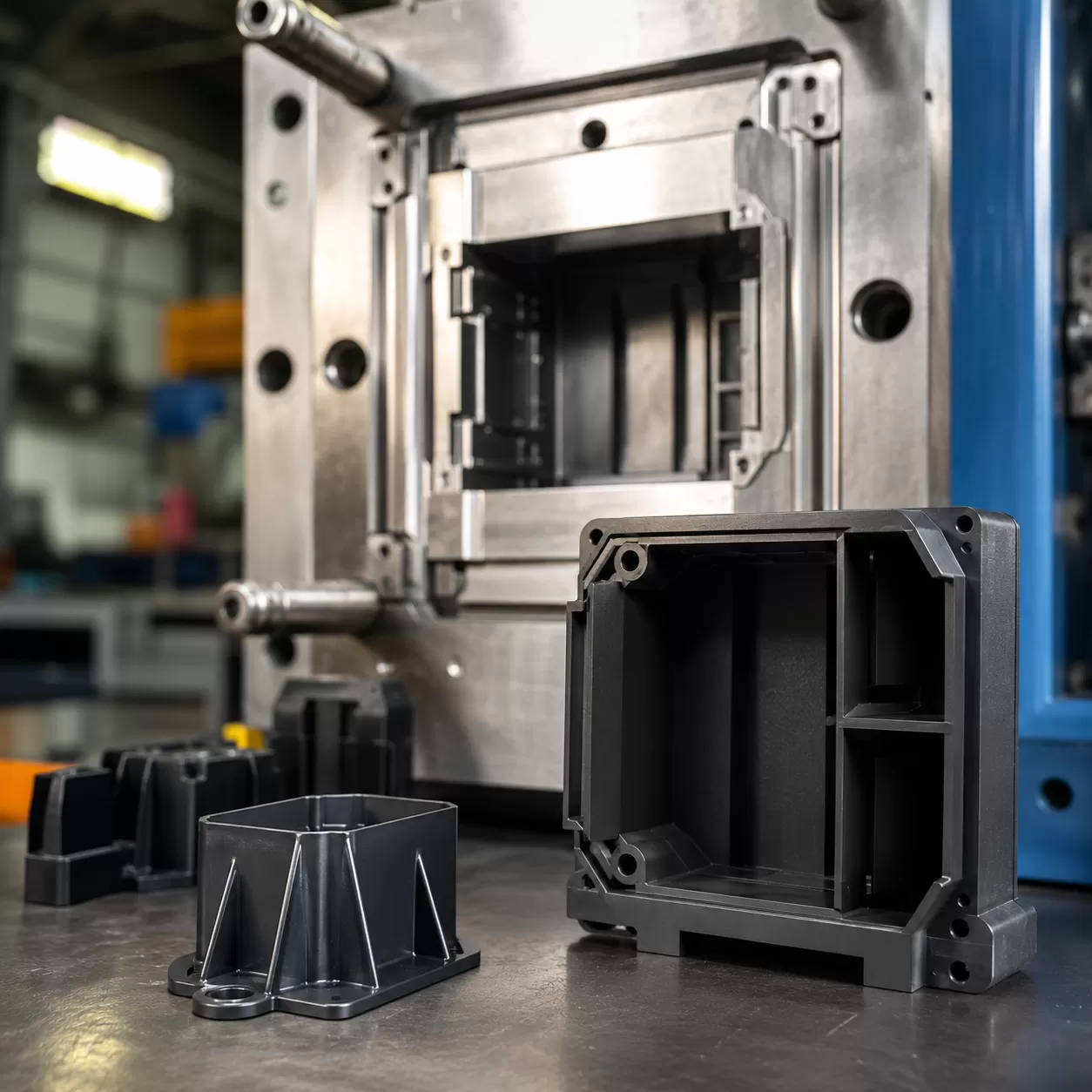
Corner design also affects the cost and reliability of the mold itself. If the mold requires an inaccessible sharp inside pocket, the toolmaker may need EDM, special electrodes, smaller cutters, additional polishing, or slower finishing operations.
Designing for the CNC Cutter
Round end mills cannot cut perfectly sharp internal corners in mold steel. A corner radius slightly larger than the cutting-tool radius lets the tool maintain feed, reduces chatter, and improves surface finish. When very small radii are unavoidable, expect slower cutting, smaller tools, EDM, or additional hand finishing.
- Match the radius to available tools: Avoid forcing the mold maker into custom tooling for nonfunctional sharp corners.
- Increase radii in deep cavities: Tool reach and deflection become the limiting factors.
- Use advanced machining only where needed: Complex mold cores may justify 5-axis CNC machining, EDM, and controlled polishing, but only for features that truly require it.
For highly shaped mold areas, HXCNC can support mold core complex cavity components and other precision tooling inserts.
Rib and Boss Junction Fillets
Ribs and bosses need radii at their bases, but too much radius can create a thick mass and sink on the opposite surface. The target is a controlled transition, not a bulky junction.
| Feature Junction | Typical Starting Radius | Primary Goal |
|---|---|---|
| Rib-to-wall base | ~25% to 40% of nominal wall thickness | Reduce stress while limiting sink risk. |
| Boss-to-wall base | ~25% to 50% of nominal wall thickness | Improve strength and ejection without excessive mass. |
| Snap or clip root | Often larger, based on strain calculation | Prevent fatigue cracking during repeated deflection. |
Gating Near Corners
Gate position influences shear, fiber orientation, weld-line location, and residual stress. Placing a gate directly into a tight corner can create a high-shear entry, jetting, surface blush, or weak orientation pattern.
- Allow the melt front to develop before it encounters major corner transitions.
- Avoid directing high-velocity flow at a cosmetic or load-bearing corner.
- Review fiber orientation for reinforced polymers near gates, ribs, bosses, and snap features.
- Use mold-flow simulation or short-shot trials for high-risk geometries.
CAD Corner Review Checklist
- Nominal wall: Identify the true wall thickness before selecting an inside radius.
- Inside radius: Start near 0.5T for structural corners, then adjust for material and function.
- Outside radius: Use the mirror principle where uniform wall is required.
- Ribs and bosses: Add root fillets without creating sink-prone thick zones.
- Material: Increase caution for amorphous, brittle, glass-filled, or chemically exposed polymers.
- Tooling: Confirm mold cavity radii can be CNC machined, polished, cooled, and maintained.
- Gating: Avoid high-shear gate entry directly into critical corners.
- Ejection: Pair radii with adequate draft and ejector support.
Frequently Asked Questions
What is the minimum corner radius for injection molded plastic parts?
There is no absolute universal minimum. A practical floor such as 0.5 mm or 0.020 in is sometimes used for early DFM screening, but the correct radius depends on material, wall thickness, load, mold construction, cosmetic requirements, and tool access. Structural corners should usually be evaluated by R/T ratio rather than a fixed number.
How do sharp internal corners affect ejection and part sticking?
As plastic cools, it shrinks around cores and steel features. Sharp transitions increase friction and local stress during ejection, especially when draft is insufficient. The result can include stress whitening, ejector marks, warpage, cracking, or parts sticking in the mold.
Can process parameters fix sharp-corner structural failure?
Process changes can reduce some cosmetic symptoms, such as minor sink, gloss variation, or incomplete filling, but they cannot remove the geometric notch. If the corner itself creates excessive stress concentration, the durable solution is a geometry change or mold modification.
When should a sharp corner be allowed?
Sharp corners may be acceptable on nonfunctional exterior styling edges, parting-line details, or features that are lightly loaded and manufacturable. Even then, tooling, polishing, ejection, and wear should be reviewed. For functional load paths, add the largest radius the design can tolerate.