
Product Category
Up to 12 Steps · IT5 Brg Seat · ↗ 0.005 · 1-Setup
SS / 001 — 008
Multi-Step CNC Turned
Stepped Shafts
Precision CNC turned and ground stepped shafts with up to 12 diameter steps, keyways, splines, threads, and bearing seats — all in one 5-axis turn-mill setup. OD tolerance IT5 on bearing seats, step shoulder runout ≤ 0.005 mm, Ra 0.4 µm ground finish. Concentricity ≤ 0.005 mm TIR between all steps.
IT5
Brg Seat Tol.
≤0.005mm
Step Runout
12 Steps
Max per Shaft
PART DWG · SS-000 GEARBOX INPUT SHAFT · 7 STEPS · 42CrMo4
ISO 9001 · 5-AXIS TURN-MILL · 1 SETUP
7 Steps · 1 Setup
↗ Runout ≤ 0.005
Gearbox · Motor · EV · Pump · Robot · Aero · Optical
Use Cases
42CrMo4 · 20CrMnTi · C45 · SUS316L · Al 7075 · Ti Gr5
Materials
48hr Quote · 5-Day Proto
Service
IT5
Bearing Seat Tolerance
OD ground in 1 setup
OD ground in 1 setup
≤0.005mm
Step Runout
concentricity all diameters
concentricity all diameters
12 Steps
Max Diameter Steps
any profile combination
any profile combination
5 Days
Fastest Delivery
prototype orders
prototype orders
Our Work
Request Similar Part →
Stepped Shafts We Have Made
Precision CNC machined stepped shafts for automotive, robotics, aerospace, medical, and industrial applications.
 42CrMo4 · Gearbox
Stepped Input Shaft — Gearbox
6 steps · Ø12–55mm · Keyway · Spline · 200 pcs
 C45 · Motor
Stepped Motor Shaft — BLDC
4 steps · Ø8–32mm · D-flat · 500 pcs
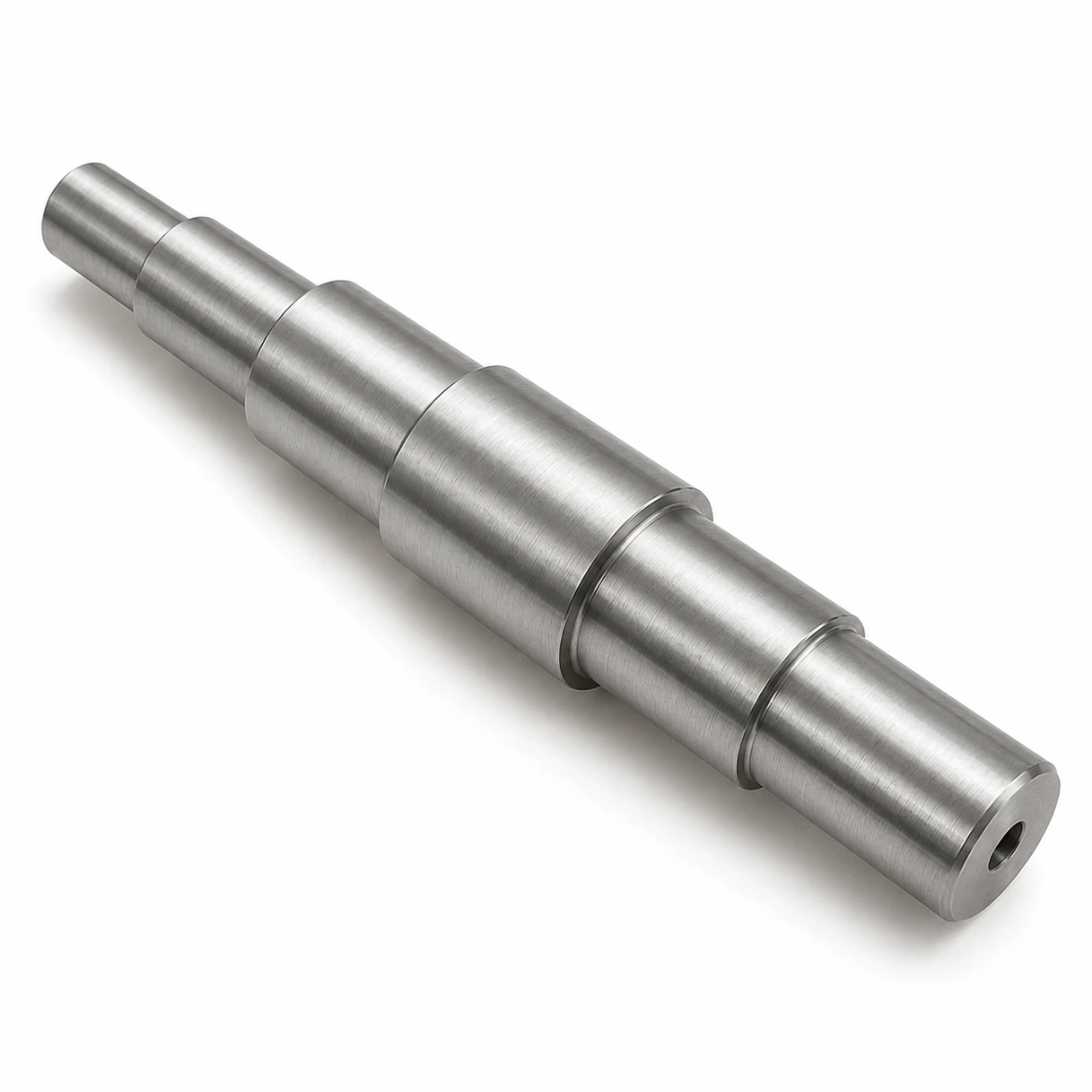 SUS316L · Pump
Stepped Shaft — Centrifugal Pump
5 steps · Passivated · 80 pcs
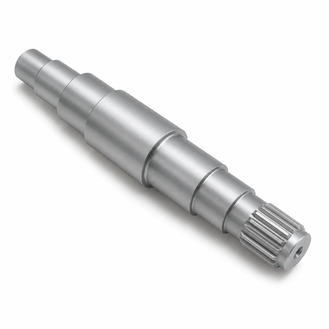 Al 7075 · Robot
Stepped Robot Arm Shaft
6 steps · Ø6–28mm · Anodized · 60 pcs
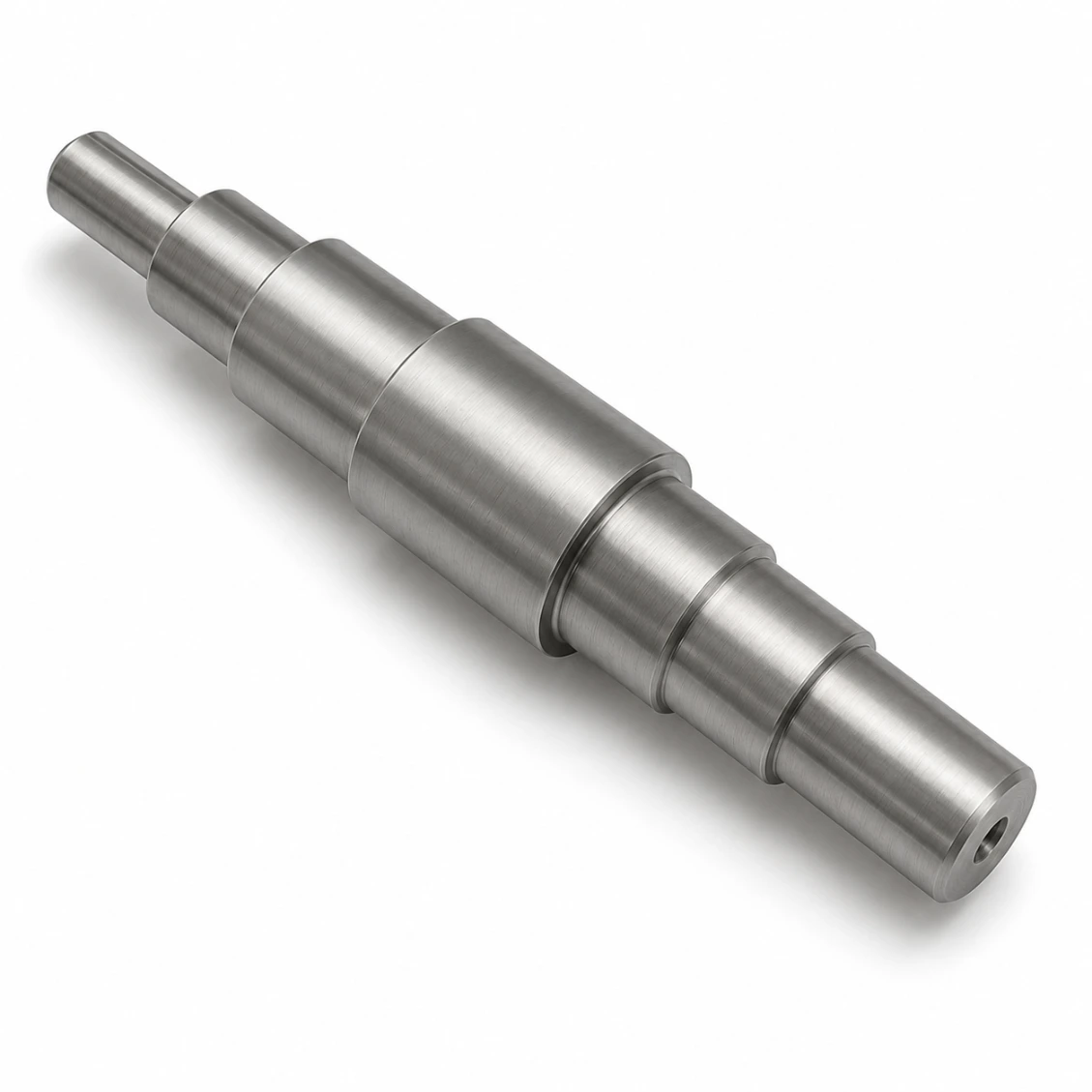 Ti Grade 5 · Aero
Stepped Shaft — Flight Actuator
7 steps · ±0.003mm · 15 pcs
 20CrMnTi · Drive
Stepped Drive Shaft — EV
8 steps · Carburized HRC60 · 300 pcs
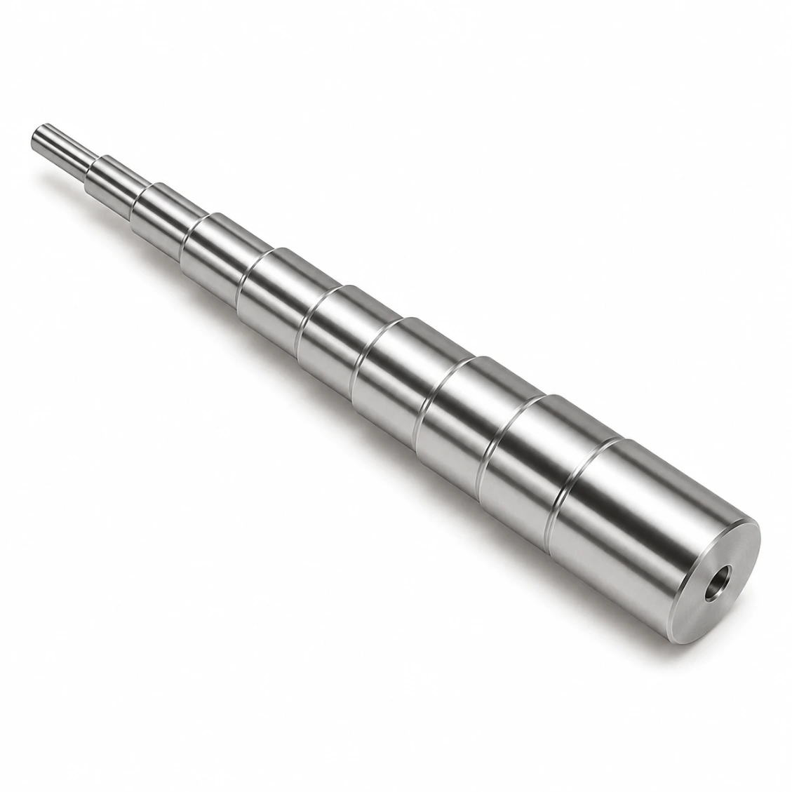 SUS303 · Instrument
Stepped Shaft — Optical Instrument
10 steps · Ø2–18mm · Ra 0.2µm · 40 pcs
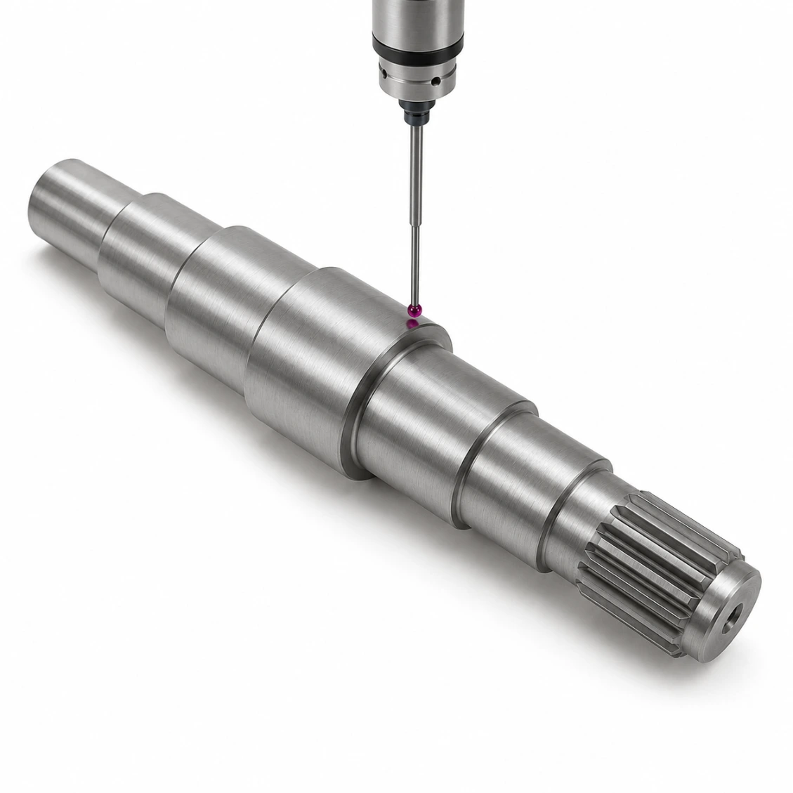 CMM Full Report
All Steps Verified
Every diameter CMM measured
How It Works
From Drawing to Finished Part
Upload your drawing — material, tolerances, and surface treatment. Quote in 48 hours.
01
Upload Drawing
STEP, DXF, PDF, or sketch with key dimensions and tolerances.
02
Quote in 48h
Material, process, surface treatment, and firm lead time.
03
CNC Machine & Inspect
Precision turning, grinding, CMM verification, surface treatment.
04
Ship Worldwide
Full dimensional report. DHL / FedEx / sea freight.
Reviews
Trusted Stepped Shafts Manufacturer
★★★★★
"Excellent dimensional consistency across every batch. CMM report matched our incoming inspection perfectly. Lead time as promised."
AK
Alex K.
Mechanical Engineer · Germany
★★★★★
"HXC's DFM review caught two design issues before production. Finished parts were perfect first time. Strongly recommended."
SL
Sophie L.
Design Engineer · France
★★★★★
"Three years sourcing precision shafts from HXC. Quality consistent, lead times reliable, engineers always responsive."
JT
James T.
Senior Engineer · UK
FAQ
Stepped Shafts — Frequently Asked Questions
Technical and sourcing questions answered by our engineers.
A stepped shaft is a shaft with multiple cylindrical sections of different diameters, connected by shoulders (steps). Each step serves a different function: bearing seat, gear fit, seal running surface, thread zone, or coupling end. Stepped shafts are the most common shaft type in gearboxes, motors, and actuators — a single shaft combines all these functions, avoiding the need for multiple mating parts.
Concentricity (coaxiality) between all stepped diameters ensures that bearings, gears, and couplings mounted on different steps all share the same rotational axis. Poor concentricity creates a bent-shaft condition — even if every individual diameter is within tolerance — causing vibration, premature bearing wear, and noise. HXC machines all stepped shaft diameters in a single 5-axis turning-milling setup, achieving concentricity ≤ 0.005 mm TIR between all steps.
Individual bearing seat diameters: IT5 (±0.005–0.010 mm depending on diameter) ground after hardening. Step shoulder runout to adjacent bearing seat: ≤ 0.005 mm. Thread runout: ≤ 0.01 mm. Spline or keyway positional tolerance: ≤ 0.010 mm. All measurements reported by CMM.
Yes — internal features including centre bores, axial through-holes, radial cross-holes, internal threads, and blind bores are all machined in the same setup as the external stepped profile. Common examples: stepped shafts with internal coolant through-bore; hollow stepped shafts with internal keyway; stepped shafts with axial M6 tapped holes for end-cap fasteners.
Prototype (1–5 pcs, turned + ground): 5–8 days. Small batch (10–50 pcs): 8–12 days. Production (100–1,000 pcs): 10–16 days. Stainless or titanium: add 2–4 days. Rush production available.
42CrMo4 (induction hardened) for industrial and automotive. 20CrMnTi (carburized) for maximum surface fatigue and EV drivetrain. C45 for BLDC and general motor shafts. SUS303/316L stainless for food, pharma, marine. Al 6061/7075 hard-anodized for lightweight. Ti Grade 5 for aerospace/medical.
Standard ground OD: Ra 0.4 µm. Precision bearing seats: Ra 0.2 µm. Mirror finish for seals: Ra 0.1 µm. All measured by contact profilometer and reported on the inspection certificate.
Yes — keyways, splines, threads, cross-holes, flats, and tapers are all machined in the same 5-axis turning-milling setup, ensuring concentricity between all features within 0.003 mm TIR.
Maximum shaft length between centres: 1,200 mm. For shafts over 600 mm, straightness correction after heat treatment is performed before final grinding. Specify the required straightness tolerance on your drawing.
A complete stepped shaft drawing should show: every diameter with tolerance and surface finish; every step shoulder with perpendicularity and runout callout relative to the bearing seat datum; all thread specifications (standard, pitch, class); keyway/spline profile and standard; and hardness requirement for each zone. HXC engineers can help interpret incomplete drawings — send a sketch and we will confirm geometry before quoting.