
Product Category
±0.003mm Profile · Matched Sets
CYC / 001 — 004
Cycloidal Wheel
Parts & RV Sets
Precision CNC machined cycloidal wheel parts — cycloidal discs, pin housings, output pin flanges, and eccentric bearings for RV and cycloidal speed reducers. Profile ground to ±0.003 mm, case hardened steel and bearing steel.
±0.003mm
Profile Tolerance
HRC 60
GCr15 Bearing Steel
10–200:1
Reduction Ratio
PART DWG · CYC-000 CYCLOIDAL DISC ASSY
ISO 9001 : 2015
Z = 30 lobes
31 outer pins
All lobes engaged
Disc · Pin Housing · Output · Bearing
Components
GCr15 · 20CrMnTi · SUJ2 · 42CrMo4
Materials
48hr Quote · MOQ 1
Service
±0.003mm
Cycloidal profile
Matched
Disc + housing set
GCr15 / 20CrMnTi
Bearing steels
10 Days
Typical lead time
Our Work
Request Similar Part →
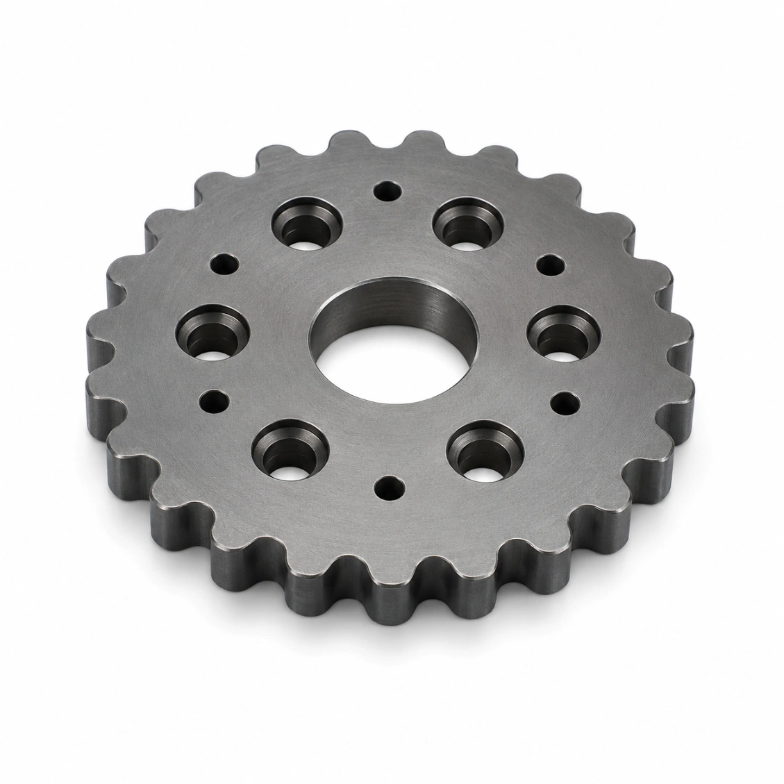
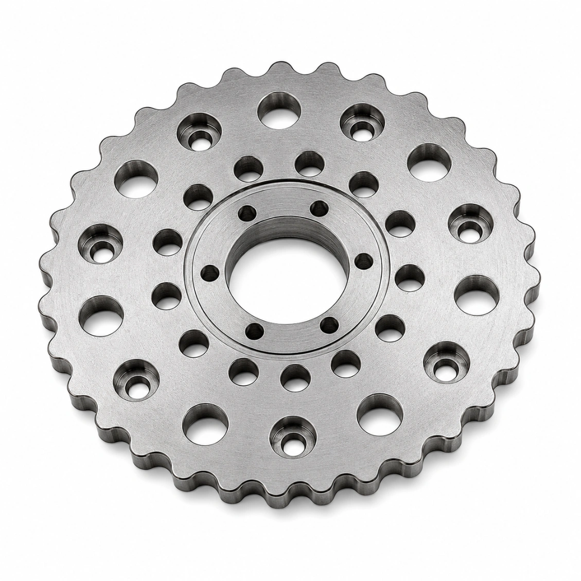
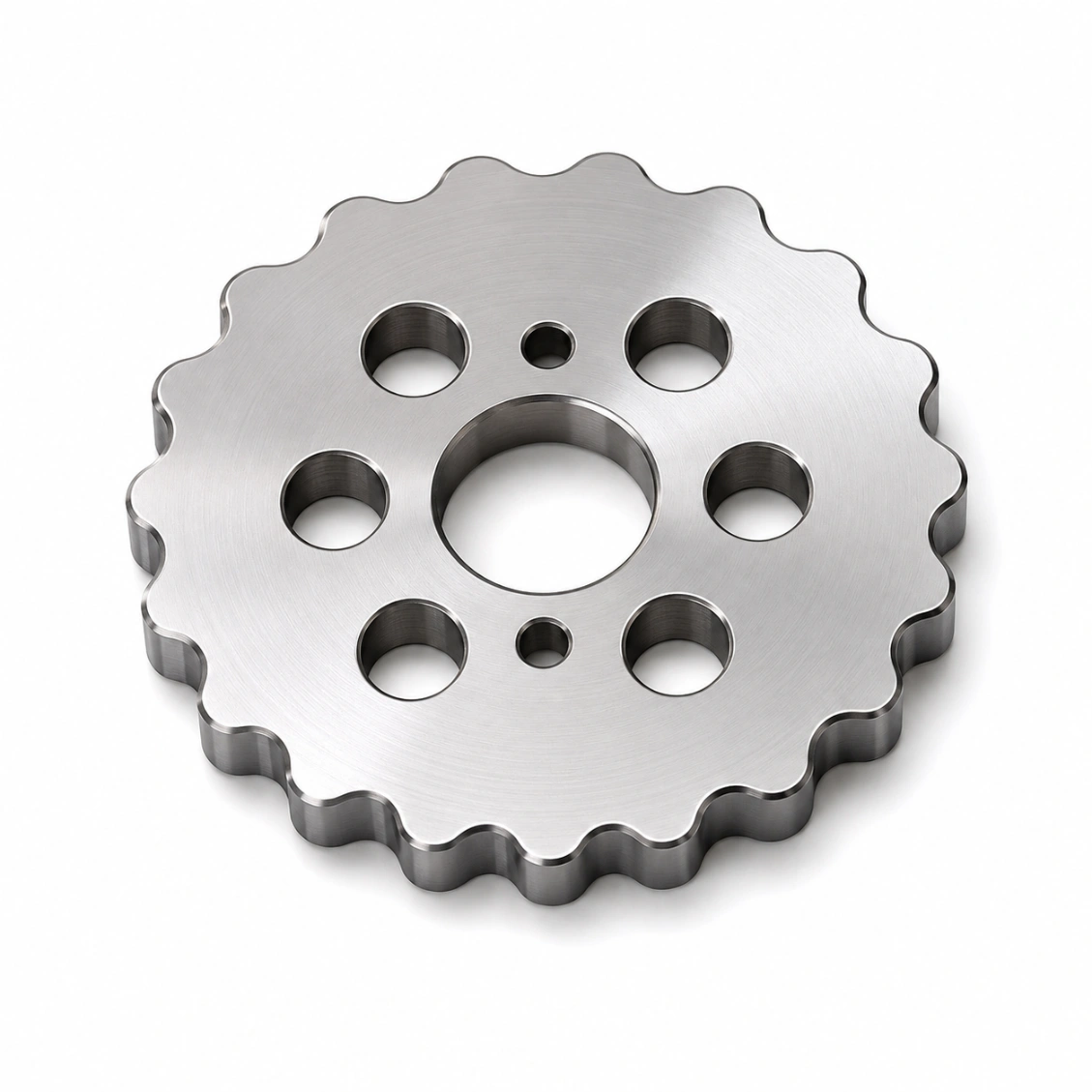
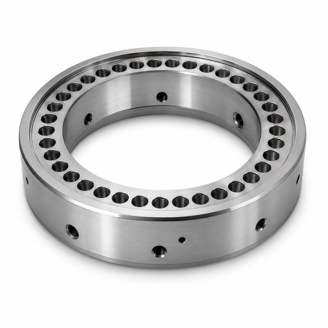
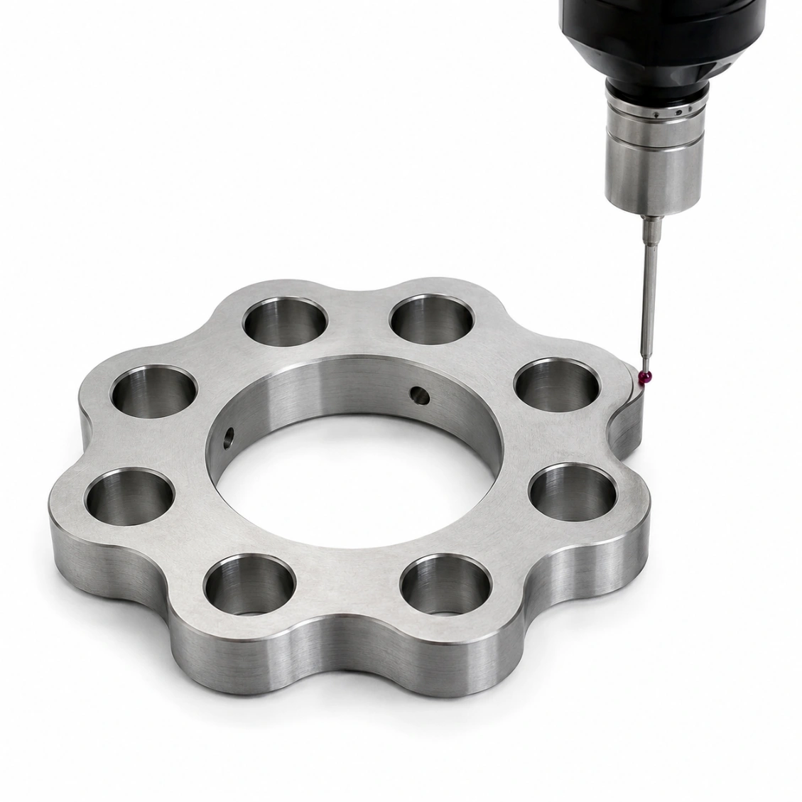
Cycloidal Wheel Parts We've Made
Ground cycloidal discs, pin housings, and output flanges for RV reducers, robot joint cycloidal drives, and precision industrial speed reducers.


How It Works
From Drawing to Finished Cycloidal Wheel Parts
Upload your cycloidal wheel parts drawing — dimensions, tolerances, material, and surface treatment.
01
Upload Drawing
STEP, DXF, PDF, or sketch with key dimensions.
02
Quote in 48h
Material, process, surface treatment, lead time.
03
CNC Machine & Inspect
Precision machining, heat treatment, surface treatment, CMM verification.
04
Ship Worldwide
Full dimensional report. DHL / FedEx / sea freight.
Reviews
Trusted Cycloidal Wheel Parts Manufacturer
★★★★★
"Excellent quality cycloidal wheel parts from HXC. Dimensional report matched our CMM on every piece."
AK
Alex K.
Mechanical Engineer · Germany
★★★★★
"HXC's DFM review saved us two design iterations. Finished cycloidal wheel parts were perfect first time."
SL
Sophie L.
Design Engineer · France
★★★★★
"Three years sourcing cycloidal wheel parts from HXC. Consistent quality, reliable lead times."
JT
James T.
Senior Engineer · UK
FAQ
Cycloidal Wheel Parts — FAQ
Common questions about cycloidal reducers, disc profile accuracy, and machining.
Cycloidal wheel parts are the precision components that form the heart of a cycloidal speed
reducer — a type of planetary gearbox where the planet (cycloidal disc) has a hypocycloid
profile and rolls inside a ring of pins rather than gear teeth. The main components are:
cycloidal disc(s) — the eccentric planet, one or two per stage; pin housing
(outer ring) — cylindrical housing with precision bores holding the outer pins; output
pin flange — picks off the output motion from holes in the cycloidal disc; eccentric
bearing — creates the eccentric orbit of the disc.
Cycloidal reducers have several advantages: High reduction ratio in one stage
(10:1 to 200:1) compared to 3:1–10:1 for a single planetary stage. High torque density
— all lobes are in contact simultaneously (50–70% of lobes engaged), vs. 2–3 teeth for a planetary.
Zero backlash achievable — the cycloidal profile is a conjugate fit with the pins, so
there is no tooth backlash in the traditional sense. High shock load tolerance — used
in robot joints that experience impact loads. These advantages make cycloidal drives standard in
collaborative robot wrists, RV reducers for industrial robots, and AGV drives.
Cycloidal disc profile accuracy is the most critical manufacturing tolerance: ±0.005 mm
for standard industrial cycloidal reducers. ±0.003 mm for robot joint RV reducers and
precision servo drives. ±0.002 mm or better for the highest-precision harmonic-competing
drives. Profile accuracy is measured point-by-point with a CMM at 1° angular increments and reported as
a radial deviation map. HXC provides this report with every cycloidal disc order.
GCr15 (52100 bearing steel): the standard for high-performance cycloidal discs —
through-hardened to HRC 58–62, excellent dimensional stability, Ra 0.2 µm achievable after superfinishing.
20CrMnTi carburized to HRC 58–62: used in RV reducers where a tough core is needed
under shock loads. Bearing steel SUJ2: Japanese-standard bearing steel equivalent to
GCr15, used in robot RV reducers. 42CrMo4: for larger heavy-industrial cycloidal drives
where GCr15 is impractical in large sections. Never use unhardened steel for production cycloidal discs
— the lobe flanks will wear rapidly under the high contact stresses.
The eccentricity is the offset between the cycloidal disc centre and its rotation axis
— which equals the eccentric bearing eccentricity. The eccentricity (e) is a fundamental design
parameter: too large → higher contact stress on each pin; too small → difficulty manufacturing the
cycloidal profile. Typical eccentricity for robot joint RV reducers: 1–3 mm. The eccentricity, lobe
count, pin count (= lobe count + 1), and pin circle radius together define the complete cycloidal drive
geometry. HXC engineers can calculate eccentricity from your reduction ratio and envelope size
requirements.
Yes — HXC supplies matched cycloidal disc(s) + pin housing + output pin flange sets
measured together to confirm the correct pin-to-lobe clearance and output pin-to-disc hole clearance.
All three components are produced in the same facility in coordinated production runs, ensuring the
assembly clearances are within the design specification. Sets are bagged together with a single
inspection report. This is particularly important for robot joint applications where incorrect clearance
causes backlash or binding.
Cycloidal profiles are generated by 5-axis CNC milling from the mathematical profile
equations (hypocycloid modified by the pin radius equidistant curve), followed by profile
grinding to remove the heat treatment distortion and achieve the final tolerance. The CNC
program is generated directly from the cycloidal geometry equations — the profile is not drawn manually
but calculated. After hardening, the profile is ground on a CNC profile grinder using a small-diameter
grinding wheel (typically Ø5–10 mm) that can follow the tight convex / concave curves of the cycloidal
lobe profile.
Single-disc cycloidal stages: one cycloidal disc per stage, simpler and lighter, but
produces an inherent unbalanced input force and torque ripple. Used in low-cost reducers.
Double-disc (180° offset) stages: two cycloidal discs phased 180° apart on the same
eccentric shaft, cancelling the input unbalance force and halving torque ripple. Standard for robot
joint RV reducers and precision servo drives. HXC machines both single and double disc configurations —
for robot joint applications, always specify double disc.
The clearance between the cycloidal disc lobe and the pin housing pins determines the backlash
of the reducer. For zero-backlash designs: the cycloidal disc is designed with a slightly
smaller pitch than the pin circle (negative clearance fit) — the disc is preloaded against the pins.
This requires very precise matching between disc profile and pin housing, which is why matched sets are
important. Standard industrial reducers: 5–15 µm pin clearance. Robot joint RV reducers: 0–5 µm
(near-zero or preloaded). HXC measures pin clearance in each matched set and reports it on the inspection
certificate.
Single cycloidal disc prototype (5-axis milled, unhardened): 7–10 days. Profile-ground, hardened disc:
12–18 days. Matched set (disc + housing + flange): 14–20 days. Double-disc stage set: 16–22 days. Rush
production available for single discs — contact us with your timeline.