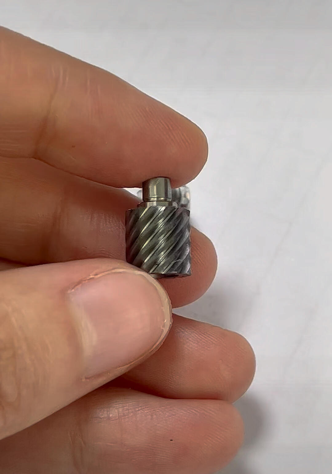
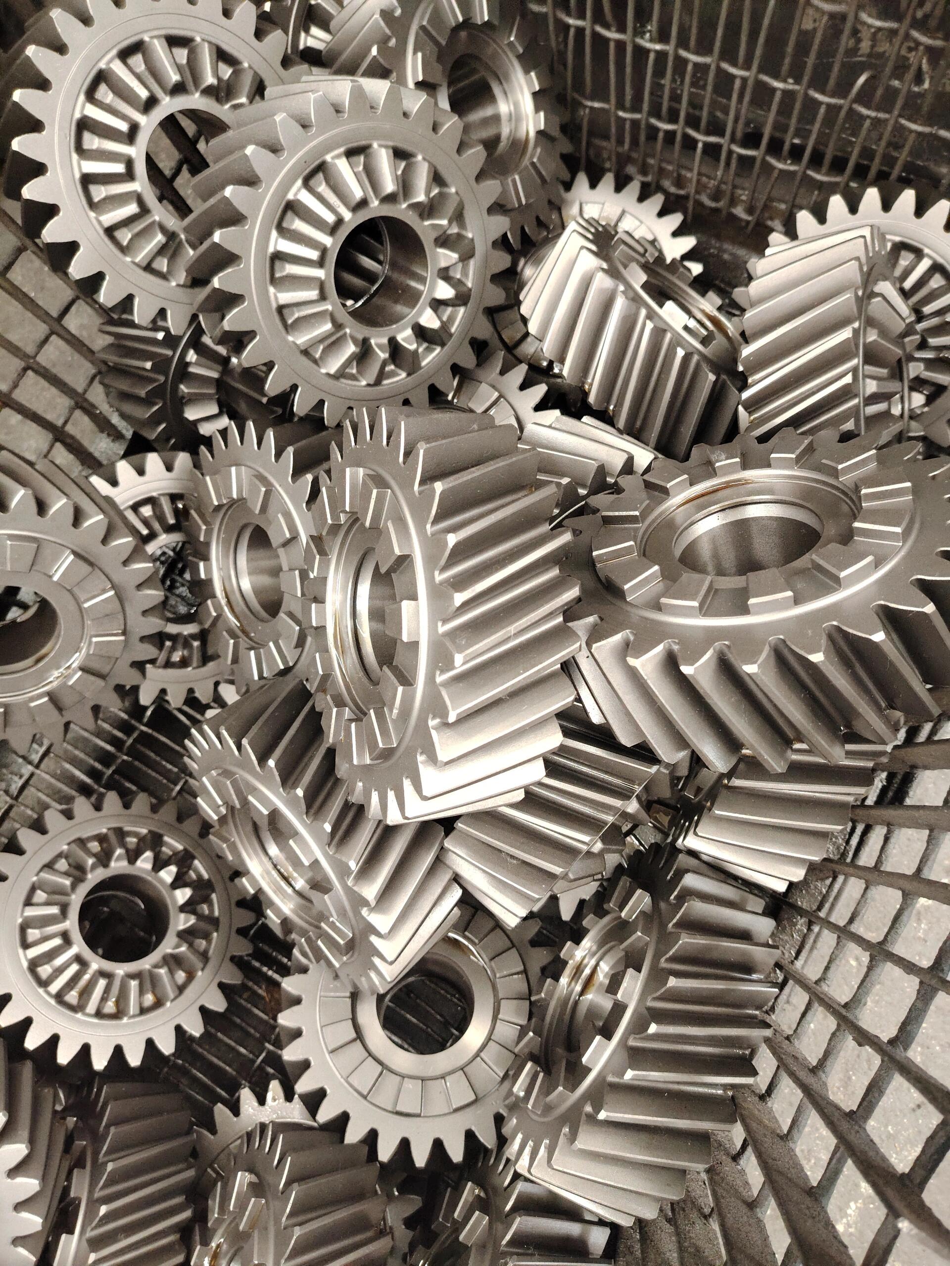
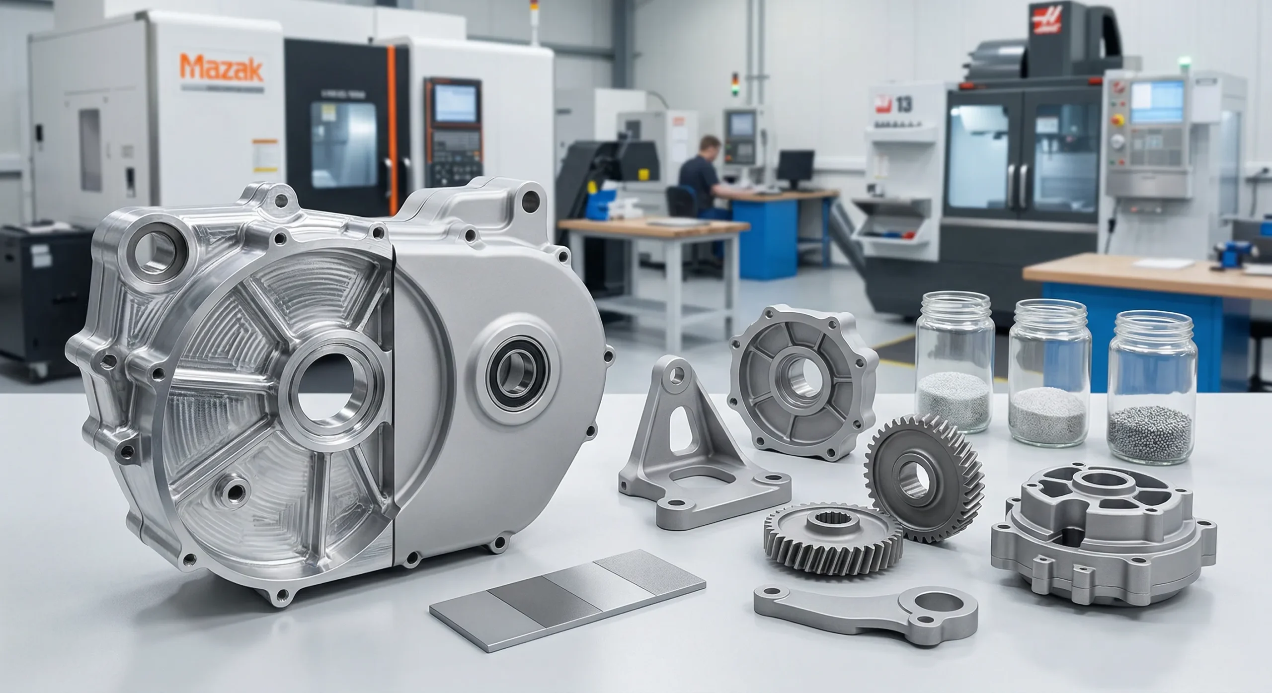
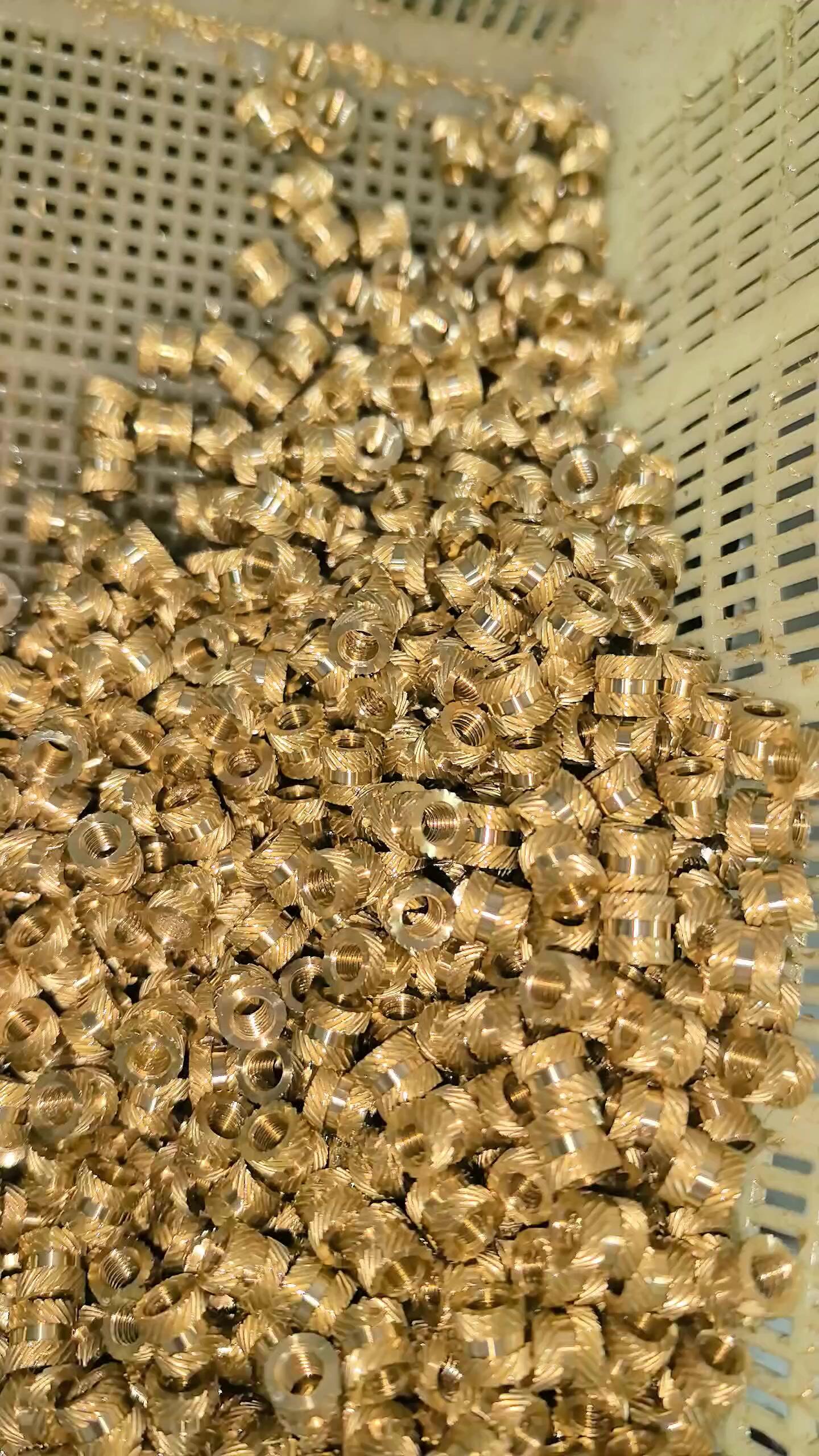
High-performance helical gears — single, double helical (herringbone), internal helical ring gears, helical pinion shafts, crossed helical, and helical rack-and-pinion sets — manufactured to DIN / AGMA standards. Helix angles 5°–45°, module 0.5–20 (metric or inch), left or right hand. Quieter, stronger, and longer-lasting than spur gears.
Single, double helical, internal ring, pinion shafts, crossed, racks, sector — any helical gear configuration your design calls for, in any quantity from a single prototype to 50,000-piece wholesale production.
Single Helical Gears
The standard external helical gear — teeth cut at a single helix angle (typically 15°–25°). The default for inline helical gear reducers, automotive transmissions, and most industrial drives. Left or right hand on request.
ExternalLH / RH
Double Helical (Herringbone) Gears
Two opposing helices on one blank — axial thrusts cancel completely, no thrust bearings needed. The premium choice for high-power compressor drives, marine propulsion, and heavy industrial reducers. Customized double helical gears in any module.
Zero ThrustHeavy Power
Internal Helical & Ring Gears
Helical teeth cut on the inside of a ring — essential for compact planetary gearboxes, integrated wheel hubs, and high-ratio inline helical gear reducers. Manufactured by gear shaping, broaching, or wire EDM in any helix angle.
Ring / AnnularPlanetary
Helical Pinion Gears & Gear Shafts
Helical pinions and precision helical gear shafts machined as a single part for maximum concentricity (TIR ≤ 0.008 mm). Standard for helical gear motors, helical geared motors, and high-torque servo drives.
Integrated ShaftConcentric
Crossed Helical Gears
Motion transmission between non-parallel, non-intersecting shafts — typically at 90°. Both gears use the same hand; shaft angle equals the sum of helix angles. Used in valve drives, distributor shafts, and instrumentation.
90° ShaftsNon-Parallel
Helical Rack & Pinion Sets
Helical gear racks paired with matching helical pinions for high-load, low-noise linear motion. Significantly quieter than spur rack-and-pinion at high speeds. Standard for CNC machine tool axes, gantries, and lifting tables. Metric and inch.
Linear MotionCNC Drives
Helical Sector Gears
Partial-arc helical gears for limited-rotation applications — throttle controls, valve actuators, automotive steering quadrants, and indexing mechanisms. Same precision as full helical gears, machined only over the working arc.
Partial ArcValve / Throttle
Miniature, Small & Large Helical Gears
From miniature helical gears (M 0.3, sub-10 mm OD) for medical and optical instruments, to large diameter helical gears (OD up to 600 mm) for wind-power and heavy industrial drives. Full range in steel, brass, stainless, aluminum, and plastic.
M 0.3–20OD ≤ 600mm
Technical Specs
Helical Gear Machining Capabilities
From high-volume CNC helical gear hobbing to ultra-precision profile grinding — we cover single helical, double helical, crossed helical, and helical rack-and-pinion. CNC milling helical gear options available for short-run and custom geometries.
⚙️
Helical Hobbing
High-volume production
🔬
Profile Grinding
DIN 4–5 precision
🏭
5-Axis Milling
Double helical & custom
📐
Helical Rack Milling
Rack & pinion sets
CNC Helical Gear Hobbing
CNC hobbing centres use angled hob heads to generate precise helical (helical-cut) tooth forms in a single pass. The most economical method for metric helical gears, standard helical gears, and high-volume helical gear sets where wholesale pricing matters. Consistent helix angle accuracy across batches up to 50,000 pcs.
Module range
0.8 – 16 mm
Helix angle
5° – 45° (left or right hand)
Max OD
600 mm
Max face width
300 mm
Quality grade
DIN 7–9 standard
Profile tolerance
±0.012 mm
Typical quantity
100 – 50,000 pcs
Lead time
7 – 14 days
Helical Gear Profile Grinding
Post-hobbing or post-hardening profile grinding for precision ground helical gears used in helical gear reducers, inline helical gear reducers, and helical gear motors. Achieves DIN 4–5 and Ra ≤ 0.4 µm on helical tooth flanks — the gold standard for ground helical gears in aerospace and high-torque drives.
5-axis CNC milling for double helical gears (herringbone), crossed helical gears, internal helical gears, custom helix angles, and helical sector gears. All features — bores, keyways, flanges — completed in one setup for maximum concentricity. The fastest path from drawing to first article for custom helical gear manufacturing.
Module range
1 – 20 mm
Helix angle
Any angle, left or right
Max OD
500 mm
Double helical
Yes — herringbone profile
Internal helical
Yes
MOQ
1 pc
Lead time (proto)
5 – 10 days
Materials
All metals + plastics
Helical Gear Rack Milling
Precision helical gear racks and matching helical pinions for rack-and-pinion drives. Racks are machined from flat or round bar stock, hardened, and ground to match your helical pinion helix angle exactly. Inch and metric helical gear racks available.
Module range
1 – 12 mm
Helix angle
14.5° – 25° standard
Max rack length
2,000 mm (spliced)
Accuracy
DIN 7 – DIN 9
Rack material
C45, 42CrMo4, SUS304
Matched pinion
Yes — supplied as a set
Lead time
10 – 16 days
Surface treatment
Black oxide, zinc, induction hardened
Materials
50+ Certified Materials
Full mill certificates and spectral analysis on every batch — steel, stainless, brass, bronze, aluminum, and engineering plastics.
Metals
Engineering Plastics
20CrMnTi Steel
Case-hardened, HRC 58–62 surface. The default steel helical gear material for automotive transmissions and hardened heavy-duty drives.
High LoadHardenedAutomotive
42CrMo4 Carbon Alloy Steel
Through-hardened, excellent fatigue resistance. Standard carbon steel helical gears for industrial helical gear shafts and heavy reducers.
Self-lubricating plastic helical gears, low friction, often run dry. The default for quiet automation drives.
Self-lubricatedLow Noise
Nylon PA66-GF30
30% glass-filled nylon helical gears for higher load capacity. Machined plastic helical gears with full tooth precision.
High StrengthLightweight
PEEK
Chemical-resistant PEEK helical gears, rated to 260°C. Sterilizable miniature helical gears for surgical and lab instruments.
High TempChemical Res.
Reference
Helical Gear Standard Specifications
Module, helix angle, pressure angle, tolerance — the standard helical gear dimensions and specifications every drawing should define. A working reference for engineers preparing CAD, RFQs, and helical gear quotations.
📏Standard Helical Gear Modules (Metric)
Per ISO 54 / DIN 780, the same standard module series applies to helical gears as to spur gears — but for helical gears it always refers to the normal module (mₙ), measured perpendicular to the tooth flank, not the transverse module:
Series I (preferred)
Series II
Typical Use
0.5, 0.8, 1, 1.25, 1.5
0.55, 0.7, 0.9, 1.125, 1.375
Miniature helical gears, instruments
2, 2.5, 3, 4, 5
1.75, 2.25, 2.75, 3.5, 4.5
Industrial helical gears, automotive
6, 8, 10, 12, 16, 20
5.5, 7, 9, 11, 14, 18
Heavy reducers, large diameter helical gears
⊕Diametral Pitch (Inch System)
For inch helical gears, normal diametral pitch (Pₙ) defines tooth size — the number of teeth per inch measured along the normal plane:
DP (normal)
Module mn (mm)
Typical Use
20, 24, 32, 48
1.27 → 0.53
Instruments, model drives
10, 12, 16
2.54 → 1.59
Robotics, small machines
5, 6, 8
5.08 → 3.18
Industrial helical gearboxes
2, 2.5, 3, 4
12.7 → 6.35
Heavy industrial reducers
∠Helix Angle & Pressure Angle
The helix angle (β) is the defining parameter of a helical gear. Standard ranges and typical applications:
Helix Angle β
Use Case
Trade-off
5° – 10°
Low-thrust drives
Modest noise gain over spur
15° – 25°
Industrial / automotive
Optimal balance — default range
30° – 40°
High-speed turbines
Needs thrust bearings or double helical
45°
Maximum smoothness
Very high axial thrust
Pressure angle: 20° normal is the global standard; 14.5° appears in legacy designs; 25° for high-load applications.
ƒKey Helical Gear Formulas
Normal vs transverse module — unique to helical gears:
mₜ = mₙ / cos(β) · pitch dia. d = mₙ × z / cos(β)
Centre distance for two meshing helical gears (same hand opposite, equal helix):
a = mₙ × (z₁ + z₂) / (2 × cos β)
Virtual tooth count zv = z / cos³(β) — used for strength calculation and undercut check. Axial thrust: Fa = Ft × tan(β).
✓DIN / AGMA Helical Gear Standards
Quality class controls profile error (Ff), helix deviation (Fβ), pitch error (Fp), and runout. Per DIN 3961–3967 / AGMA 2015 / ISO 1328:
A complete helical gear drawing must specify everything below — missing the hand or helix angle reference plane will block quoting:
• Normal module (mₙ) or normal DP
Required
• Number of teeth (z)
Required
• Helix angle (β)
Required
• Hand — left or right
Required
• Normal pressure angle (default 20°)
Required
• Face width (b)
Required
• Pitch / outside / root diameter
Required
• Quality grade (DIN / AGMA / ISO)
Required
• Tooth thickness / backlash
Recommended
• Material, heat treatment, surface finish
Required
Case Studies
Real Helical Gear Projects
From single-piece prototypes to high-volume helical gear sets — verified results from our customers.
Industrial
Inline Helical Gear Reducer — Stage 1 & 2
Material
20CrMnTi
Process
Hob + Grind
Helix Angle
20°
Quantity
1,500 sets
✓ DIN 6 · Noise 8 dB lower than previous spur gear design
Power Transmission
Double Helical (Herringbone) Gear Pair
Material
42CrMo4
Helix Angle
±30°
Feature
Zero axial thrust
Quantity
80 pcs
✓ Zero thrust bearing required · 40% higher torque vs single helical
Robotics
Helical Servo Gear — Robotic Arm Joint
Material
Al 7075-T6
Process
5-Axis + Anodize
Grade
DIN 5
Quantity
120 pcs
✓ FAI approved 1st cycle · backlash < 0.015 mm
How It Works
From Drawing to Your Door
Upload your helical gear drawing or CAD file — we handle DFM, process selection, and full CMM inspection from our Chinese precision machining facility.
01
Upload CAD / Drawing
DXF, DWG, STEP, IGES or PDF. Include helix angle, hand, normal module, and accuracy class.
02
Helical Gear Quote in 48 Hours
CNC machining helical gear quotation covering process (hobbing vs grinding), material, lead time, and cost breakdown. Wholesale pricing for high-volume runs.
03
Production & CMM QC
CNC helical gear cutting with in-process Klingelnberg measurement — helix deviation, profile, pitch, and runout.
04
Ship Worldwide
Vacuum-packed with full inspection report. DHL / FedEx / sea freight available.
Quality
Zero-Defect Commitment
Every helical gear leaving our Chinese precision machining facility passes a 4-stage inspection covering helix deviation, profile error, pitch accuracy, and surface finish.
Certifications & Equipment
✓
ISO 9001:2015
Quality Management System certified — ISO helical gear manufacturing throughout
📐
DIN 3961–3967 / AGMA Standards
AGMA helical gear standards and DIN tolerance classes 4–11. Helix angle deviation Fβ measured on every batch.
🔭
Klingelnberg Gear Analyser
Dedicated helical gear measurement: profile, helix, pitch, runout, lead — all reported per DIN 3962.
📄
Full Material Certification
Mill cert + spectral analysis on every material batch — critical for custom helical gear applications.
4-Stage Inspection Protocol
1
Incoming Material Check
Spectral analyzer confirms alloy grade. No substitutions — 20CrMnTi is 20CrMnTi.
2
First Article Inspection
Full Klingelnberg + CMM measurement of first helical gear — helix angle, profile, pitch error confirmed before batch.
3
In-Process Gear Measurement
Periodic checks during production. Helix deviation Fβ, profile deviation Ff, pitch error Fp — all within DIN class.
4
Final Outgoing Inspection
100% visual + sampled gear analysis. Full helical gear measurement report shipped with every order.
Reviews
Trusted Helical Gear Manufacturer
★★★★★
"We switched from a local helical gear manufacturer to HXC for our gearbox helical gears. Profile grinding quality is excellent — DIN 6 consistently achieved. Helix angle deviation was within 5 µm across all 1,500 parts. Lead time 14 days."
TW
Thomas W.
Gearbox Design Engineer · Germany
★★★★★
"HXC machined a set of double helical gears for our high-power compressor drive. The herringbone geometry was challenging but they nailed it on the first article. Zero axial thrust measured — exactly as designed. Highly recommended."
LB
Luca B.
Mechanical Engineering Lead · Italy
★★★★★
"We needed custom helical gears with a 25° helix angle in Al 7075 for our aerospace servo actuator. DIN 5, anodized, full CMM report. First article approved in one cycle. Backlash was 0.012 mm — tighter than the drawing requirement."
SR
Sophie R.
Aerospace Procurement · France
FAQ
Helical Gear — Frequently Asked Questions
Everything engineers ask about helical gears, helical gear design, and comparing helical vs spur gear or helical vs straight cut gears — answered by our team.
A helical gear is a cylindrical gear whose teeth are cut at an angle — the helix angle — to the gear's rotational axis, rather than parallel as in a spur gear. This angled tooth form means multiple teeth engage simultaneously, producing a gradual, overlapping contact pattern. The result is quieter operation, higher load capacity, and smoother transmission compared to straight-cut spur gears, at the cost of an axial thrust force that must be handled by thrust bearings. Helical gears are the dominant gear type in automotive gearboxes, industrial gear reducers, and high-speed power transmission.
An internal helical gear (also called a helical ring gear or annular helical gear) has helical teeth cut on the inside of a hollow ring rather than the outside of a cylinder. It meshes with an external helical pinion that sits inside the ring. The pinion and ring rotate in the same direction, allowing very compact reduction designs — which is why internal helical gears are the foundation of planetary gearboxes, integrated wheel hubs, and high-ratio inline helical gear reducers. Internal helical gears cannot be hobbed and must be manufactured by gear shaping, broaching, or wire EDM, which makes them more expensive than external helical gears but irreplaceable for compact, high-ratio systems.
Helical gears are used wherever smooth, quiet, high-speed power transmission is needed between parallel shafts. Key applications include: automotive gearboxes and EPS systems; inline helical gear reducers for conveyors and industrial drives; helical gear motors and helical geared motors; helical gear pumps for hydraulic and lubrication systems; aerospace actuators; robotic servo gearheads (helical servo gears); and helical gear rack and pinion systems for machine tool linear axes. Crossed helical gears transmit motion between non-parallel, non-intersecting shafts.
Helical gears transmit power between parallel shafts using angled teeth on a cylindrical body. Bevel gears — including helical bevel gears — transmit power between intersecting shafts, typically at 90°, using teeth on a conical body. A helical bevel gear combines both: conical body for shaft angle change plus helical (curved) teeth for smoother engagement. In gearbox terminology, a bevel helical gear reducer or helical bevel gear unit uses a bevel stage for the right-angle turn and a helical stage for the main speed reduction.
The classic helical gear vs spur gear (or spur gear vs helical gear) comparison: Helical gears are better for high-speed operation, low noise, high load, and smooth transmission — which is why automotive gearboxes and industrial inline helical gear reducers use them. Spur gears are better for simplicity, zero axial thrust, lower cost, and precise positioning at moderate speeds. For most continuous-duty power transmission at speeds above ~3 m/s pitch velocity, choose helical. For instruments, indexing drives, and low-speed machinery, spur gears are the practical choice.
For the same module and face width, helical gears are 20–40% stronger in bending and surface fatigue than spur (straight-cut) gears. This is because helical teeth have a longer contact line (the diagonal mesh distributes load over more tooth area) and a higher contact ratio. In the straight cut vs helical gears debate: helical wins on strength and noise; straight cut wins on simplicity and no axial thrust. Are straight cut gears stronger than helical? No — helical gears carry more load at the same tooth size.
Helical gears are better than spur gears in most continuous-duty power transmission applications: quieter (the biggest advantage of helical gears over spur gears), stronger, smoother, and capable of higher speeds. The advantages of helical gears over spur gears also include higher contact ratio and the ability to carry more torque per unit size. However, the one disadvantage of helical gears is the axial thrust force, which requires thrust-capable bearings and adds to system cost. For low-speed, low-load, or precision indexing applications, spur gears remain the simpler and cheaper choice.
Helical gears cost 10–30% more than equivalent spur gears of the same module and material. The premium comes from: more complex hobbing setup (angled hob head), higher tooling wear due to the helical cutting path, and the need for thrust bearings in the assembly. However, for high-volume production using CNC helical gear hobbing, the per-piece cost difference narrows significantly. Custom helical gears for low volumes cost more due to setup time. At HXC, we provide competitive helical gear pricing and helical gear quotes from prototype (1 pc) to wholesale production with no tooling fee.
Yes — helical gears typically outlast spur gears in comparable applications for two reasons: first, the distributed contact load reduces contact stress (Hertzian pressure) on the tooth flanks, slowing pitting fatigue; second, the gradual tooth engagement reduces dynamic loads and impact stresses that cause fatigue cracks in spur gear roots. In automotive gearboxes, the shift from spur to helical gears in the 20th century was driven partly by durability as well as noise. With proper lubrication and a correct helix angle, helical gears in good working conditions can last the lifetime of the machine.
The main disadvantages of helical gears: (1) Axial thrust — the helix angle generates a force component along the shaft axis, requiring thrust bearings or a double helical (herringbone) arrangement to cancel it. (2) Higher manufacturing cost vs spur gears. (3) More complex design — helix angle, lead, and hand must all be specified and matched between mating gears. (4) Efficiency slightly lower than spur gears due to the sliding component in helical tooth contact (though the difference is small — typically 0.5–1% per mesh). The double helical gear advantages include eliminating axial thrust at the cost of even higher manufacturing complexity.
A right hand helical gear has teeth that spiral up and away from the viewer in a clockwise direction (like a standard screw thread); a left hand helical gear spirals counter-clockwise. For external helical gears meshing on parallel shafts, one must be left hand and the other right hand — same hand will not mesh. For crossed helical gears (non-parallel shafts), both gears use the same hand. The hand must always be specified on the drawing alongside the helix angle. HXC supplies left and right hand helical gears as matched pairs, with hand verification on every CMM inspection report. Hand also affects the direction of axial thrust — useful when designing thrust bearing arrangements.
Helical gears are significantly quieter than spur gears, especially at high speeds. The angled teeth create a gradual, overlapping engagement rather than the simultaneous full-tooth impact of spur gears. Noise increases with: helix angle accuracy errors (grind to DIN 5–6 for quiet operation), bearing misalignment, inadequate lubrication, and worn flanks. At very high speeds or with large helix angles, axial vibration can become a noise source. Double helical gears are quietest because the opposing helix forces cancel, eliminating axial oscillation.
Yes — helical gears can be back-driven just like spur gears, because their tooth normal angles create low friction relative to the driving force. This distinguishes helical gears from worm gears, which are self-locking at low lead angles. The helical worm gear (crossed helical gear) is a special case: at very high reduction ratios and low lead angles on the worm element, it may become self-locking. Standard parallel-axis helical gear sets — in inline helical gear reducers or gearboxes — are always reversible and can be back-driven freely.
Yes — steel helical gears require lubrication for efficient, long-lasting operation. The sliding action between helical teeth (from the helix angle) is greater than in spur gears, generating more heat. Gear oil viscosity should be selected based on pitch-line velocity, load, and operating temperature — typically ISO VG 150–320 for industrial helical gear reducers. The exception is plastic helical gears (POM, Nylon): these are often run dry because the low-friction polymer surface and lower contact loads make lubrication unnecessary or even harmful. In miniature helical gears for instruments, a light grease application is often sufficient.
The best material depends on the application. For automotive and industrial helical gear reducers: 20CrMnTi (case-hardened, HRC 58–62) is the strongest material for helical gears under high cyclic load. For heavy-duty industrial: 42CrMo4 through-hardened. For lightweight aerospace: Al 7075-T6 or Grade 5 titanium. For helical gear pumps and food/medical: SUS316L stainless. For low-noise automation: POM plastic helical gears. For high-temperature environments: PEEK miniature helical gears. We stock and certify all these materials with full mill certificates.
For maximum surface and bending fatigue strength, case-hardened 20CrMnTi steel (carburized to 0.8–1.2 mm case depth, surface HRC 58–62, core HRC 30–45) is the standard choice for high-performance helical gears in automotive gearboxes. M2 tool steel ground to DIN 4 achieves the highest surface hardness but is more brittle. For aerospace helical gears where weight matters, Grade 5 titanium offers the best specific strength. For plastic helical gears, PEEK GF30 gives the highest strength-to-weight among engineering polymers.
The optimal helix angle for helical gears balances noise reduction, load capacity, and axial thrust. In practice: 15°–25° is the most common range for industrial and automotive gearboxes — this gives a significant improvement in contact ratio and noise over spur gears while keeping axial thrust manageable. 30°–45° helix angles (used in high-speed turbine gearboxes) maximise smoothness but require heavy-duty thrust bearings or a double helical arrangement. Standard helical gears from catalogue suppliers typically use 15° or 19.5° helix angles for interchangeability. For custom helical gears, our engineers recommend 20° as the default unless your application demands otherwise.
The 17-tooth rule states that a standard 20° pressure-angle spur gear needs at least 17 teeth to avoid undercutting. For helical gears, the effective tooth count is the virtual number of teeth (actual teeth ÷ cos³ψ, where ψ is the helix angle), which is always higher than the actual count. This means a helical gear can have fewer physical teeth than 17 without undercutting — one of the advantages of helical gears over spur gears for compact, high-ratio single-stage reductions. For example, a helical pinion with 14 actual teeth at 20° helix has a virtual tooth count of ~16.8, safely above the undercut limit. For very small tooth counts, our engineers apply profile shifting to eliminate undercutting entirely.
Get a Quote
Send Your Drawing. Get a Quote.
Every enquiry includes a DFM review — tolerance feasibility, material confirmation, and process approach confirmed before production starts. MOQ 1 piece.
24hr
Quote Response
MOQ 1
Prototypes OK
ISO
9001:2015
📐
DFM Review on Every Enquiry
Tolerance feasibility, fixturing strategy, and material confirmation. Specific, actionable feedback — not generic pushback.
🎯
First Article Inspection — Standard
FAI report on every new run. Material certs and surface treatment certs included with every shipment.
🔄
Same Process: Prototype to Production
Process plan from your prototype applies to production batches. No re-qualification when you scale.
⚙
3 / 4 / 5-Axis CNC + Turning
Complex structural parts, shafts, housings, and transmission components. Metals and engineering plastics.
ISO 9001:20153/4/5-Axis MillingCNC TurningCMM InspectionGlobal Delivery