
A machinable design respects cutting-tool geometry, workholding access, material behavior, inspection needs, and the number of setups required to complete the part.
Ignoring those constraints rarely makes a part impossible, but it often forces smaller tools, longer cycles, nonstandard cutters, secondary operations, or tighter process control. This guide explains how to preserve function while removing avoidable manufacturing cost.
Give the cutter a direct, rigid path to every critical feature.
Avoid deep, narrow, thin, or undersized geometry without a functional reason.
Apply tight tolerance and fine finish only where function requires them.
Orient features to reduce re-clamping and datum transfer.
01Core Geometry Rules for CNC Milling
Subtractive manufacturing is governed by the physical diameter, flute length, rigidity, and approach direction of the cutting tool. Designing around those limits allows standard tooling and stable process parameters to be used across HXCNC’s CNC milling services.
Internal Corner Radii
A rotating end mill cannot create a perfectly sharp internal vertical corner. Every milled pocket retains a radius related to the cutter diameter. A corner radius equal to the tool radius also forces the cutter into near-full engagement, increasing load, heat, and chatter.
- Increase the design radius: Make the internal radius larger than the anticipated cutter radius so the tool can interpolate through the corner without sudden full-width engagement.
- Use generous radii in deep pockets: Larger corners permit a larger, stiffer tool and reduce cycle time.
- Use relief geometry when a mating square corner is essential: Dog-bone or T-bone relief may be more economical than EDM, depending on appearance and assembly requirements.
Practical starting point: A corner radius around 110% or more of the selected tool radius often improves tool motion, but it is not a universal rule. Pocket depth, material, toolpath, tolerance, and available cutters must also be considered.
Pocket Depth and Tool Reach
Deep, narrow pockets require long tool overhang. Tool deflection rises rapidly as unsupported length increases, reducing dimensional accuracy and surface quality. A depth near four times the pocket width can be a useful early DFM screening threshold, but achievable depth depends on corner radius, access, tool diameter, material, and whether special reach tooling is acceptable.
Deep cavities with small corner radii combine two conflicting requirements: a long tool for reach and a small tool for corner access. Increasing the radius or opening the pocket usually saves more cost than relaxing a noncritical tolerance.
Machined Wall Thickness
Thin walls can move under cutting force, clamping pressure, residual stress, and heat. The practical minimum therefore depends on wall height, unsupported length, material modulus, stock condition, adjacent geometry, and tolerance.
| Material Category | Early DFM Screening Value | More Robust Starting Point |
|---|---|---|
| Metals | Approximately 0.8 mm for short, supported walls | 1.5 mm or greater where stiffness and yield matter |
| Machined plastics | Approximately 1.5 mm for favorable geometry | 3.0 mm or greater to better control heat and deformation |
These are quoting guidelines, not guaranteed limits. Very short metal walls can be thinner, while tall plastic walls may require substantially more thickness.
Holes and Drilled Cavities
- Prefer standard drill sizes: Common metric, fractional, letter, and number drill sizes reduce special tooling and simplify inspection.
- Control depth-to-diameter ratio: Holes up to roughly 4D are generally straightforward. Deeper holes may require peck cycles, through-tool coolant, gun drilling, or specialized drills.
- Allow the drill-point bottom: Standard twist drills leave a conical bottom. Specify a flat bottom only when assembly, flow, or seating function requires it.
- Provide breakout control: For intersecting or cross holes, consider burr access and the order of operations.
02Threads, Taps, Undercuts, and Clearances
Thread design should account for material strength, engagement length, fastener grade, loading direction, tapping access, and the method used to create the thread. This is especially important in assemblies involving a bearing mount shaft or another serviceable precision component.
Thread Engagement and Blind-Hole Depth
More engagement does not always create a proportionate increase in joint strength. For many steel fastener and metal base-material combinations, one to two nominal diameters of engagement is a useful starting range. Softer materials, inserts, high loads, fatigue, and repeated service may require a different design.
- Avoid unnecessary full-depth threading: Thread only the length needed to meet the joint calculation.
- Add tap runout: A blind hole must extend beyond the complete thread to accommodate the drill point, tap chamfer, chip space, and incomplete threads.
- Use standard thread series: Custom pitches increase tooling, programming, gauging, and replacement complexity.
- Identify insert requirements early: Helical or solid inserts change pilot-hole size, wall thickness, and installation access.
Drawing note: Dimension usable full thread separately from total drilled depth. “Tap to bottom” is not a complete manufacturing definition for a blind hole.
Avoiding Difficult Blind Undercuts
Hidden reliefs may require keyseat cutters, lollipop tools, slotting tools, EDM, or a separate turning operation. Tool neck strength and entry clearance often become the limiting factors.
- Remove undercuts that do not serve assembly, seal, retention, or clearance functions.
- Use a standard groove width and enough entry space for the cutter body.
- Consider a through-feature, split assembly, or accessible relief where the product architecture permits it.
03Tolerances, GD&T, and Surface Finish

Tolerance is a functional requirement with a manufacturing price. Tightening a dimension can affect machine selection, setup count, thermal control, inspection method, tool compensation, process capability, and scrap risk.
Cost vs. Precision
A general tolerance near ±0.005 in (±0.127 mm) may be economical for many moderate-size milled features, but it is not a universal shop standard. Part size, geometry, material, feature type, and drawing standard determine what is readily achievable.
- Use title-block tolerances for noncritical dimensions: Avoid adding individual tight callouts everywhere.
- Tighten interfaces, not entire parts: Bearing seats, seal lands, alignment datums, and controlled fits deserve more attention than clearance faces.
- Match tolerance to measurement: A requirement is incomplete if it cannot be reliably inspected.
- Expect secondary finishing where needed: Very tight size, roundness, cylindricity, or finish may require precision grinding, honing, lapping, or EDM.
Using GD&T to Protect Function
GD&T can control functional relationships without forcing every coordinate dimension to carry a small bilateral tolerance. Position, profile, flatness, perpendicularity, runout, and datum structures should reflect how the part locates and works in assembly.
A precision fluid manifold, for example, may depend on port position, sealing-face flatness, and datum relationships more than on tight tolerances applied indiscriminately to the outer block.
Over-constrained datum schemes, duplicated controls, ambiguous basic dimensions, and unnecessary zero-position tolerances can be more expensive than a genuinely tight feature.
Defining Surface Roughness
Surface roughness Ra is the arithmetic average deviation of the measured profile. It does not by itself define waviness, lay, defects, bearing ratio, or sealing performance, so functional surfaces may need additional specification.
| Nominal Finish Level | Typical Ra | Common Use | Relative Cost |
|---|---|---|---|
| General as-machined | 125 µin / 3.2 µm | Noncritical brackets, covers, and internal faces | Baseline |
| Controlled machined | 63 µin / 1.6 µm | Mating faces and moderate sliding interfaces | Low to moderate |
| Fine machined | 32 µin / 0.8 µm | Selected seal, bearing, and precision contact surfaces | Moderate to high |
| Very fine | 16 µin / 0.4 µm | Specialized sealing, optical, medical, or clean-process needs | High; often needs finishing |
Cost-control rule: Apply fine Ra requirements only to the surfaces whose friction, sealing, wear, cleanliness, or appearance depends on them.
04Material Selection and Machining Behavior
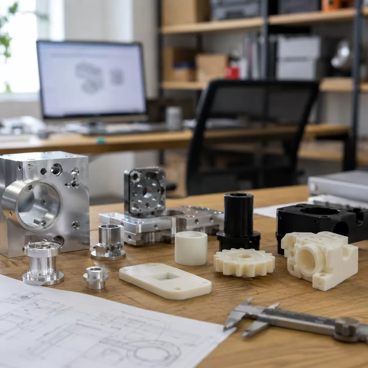
Material selection affects cutter life, chip formation, thermal distortion, burrs, achievable wall thickness, finishing, and total cycle time. Machinability ratings can help with broad comparisons, but values change by reference material, hardness, temper, composition, and testing method. They should not be treated as universal percentages.
Metal Design Profiles
- Aluminum 6061: A common economical choice with good machinability, dimensional stability, corrosion resistance, and strength-to-weight performance. See HXCNC’s aluminum machining capabilities.
- Brass C360: A free-cutting alloy that supports high productivity and excellent thread and surface quality, subject to regulatory and service requirements.
- Stainless 304/316: Corrosion-resistant but prone to work hardening and heat concentration; sharp tooling and positive cutting action are important.
- Titanium Grade 5: High specific strength and biocompatibility, but low thermal conductivity and chemical reactivity increase tooling demands.
- Nickel-based alloys: Selected for heat and corrosion performance, with high cutting forces and rapid tool wear requiring a specialized process for nickel-alloy CNC machining.
| Material | Machining Character | Design Advantage | Typical Application |
|---|---|---|---|
| Aluminum 6061 | Generally fast-cutting and predictable | Low mass and broad availability | Enclosures, brackets, frames |
| Brass C360 | Excellent chip control and productivity | Threads, conductivity, corrosion resistance | Valves, fittings, hardware |
| Stainless 304 | Work-hardening and heat-sensitive | Corrosion resistance and hygiene | Medical, food, marine equipment |
| Titanium Grade 5 | Low cutting speed and high tool demand | High specific strength and biocompatibility | Aerospace and medical components |
Machined Plastic Design Profiles
- POM / acetal: Good dimensional stability, low friction, and clean machining make it suitable for bushings, guides, and low-load gears.
- PEEK: Maintains properties at elevated temperature and in demanding chemical environments, but material cost and stress history require careful planning.
- ABS: Economical and machinable, although heat, clamping, and thin walls can produce distortion.
- Nylon: Tough and wear-resistant, but moisture absorption and thermal expansion must be considered for precision nylon machining.
053-Axis vs. 5-Axis Setup Economics

Machine selection depends on more than geometry. A simpler machine can be economical for open, prismatic parts, while a higher hourly 5-axis rate may reduce total cost by eliminating fixtures, manual reorientation, datum transfer, and in-process inspection.
3-Axis Milling
Best suited to accessible features aligned with the primary X, Y, and Z directions. It offers low setup complexity for plates, brackets, shallow pockets, and open housings.
5-Axis Milling
Useful for multi-face features, compound angles, deep cavities, short-tool access, and contoured surfaces where one setup improves positional relationships.
Minimizing Workpiece Reorientation
- Align holes, slots, and pockets along common tool-access directions where function permits.
- Provide a stable datum face and clamping region that remains available through early operations.
- Avoid unique feature angles that require dedicated fixtures unless the angle serves a functional purpose.
- Consider inspection access at the same time as cutting-tool access.
| Factor | 3-Axis Milling | 5-Axis Milling |
|---|---|---|
| Machine and programming rate | Generally lower | Generally higher |
| Reorientation | May require multiple fixtures and datum transfers | Can machine five sides in one clamping |
| Best geometry | Open, prismatic, single-direction features | Compound angles, contours, and multi-face features |
| Primary economic advantage | Simple preparation and broad capacity | Fewer setups and improved feature relationships |
A complex machined impeller is a clear multi-axis candidate because blade access, tool angle, surface continuity, and short tool reach are difficult to achieve efficiently with repeated 3-axis setups. HXCNC evaluates these parts through its 5-axis CNC machining service.
06Pre-Release DFM Checklist
Before Sending the Drawing for Quotation
- Internal corner radii accommodate a practical cutter size and pocket depth.
- Thin walls have enough support for their height, material, and tolerance.
- Blind-hole depth includes drill point, chip space, and tap runout.
- Threads use standard size and pitch unless a special form is functionally required.
- Tight tolerances are limited to functional interfaces.
- Datum features reflect assembly and inspection setup.
- Fine surface finishes identify only the necessary faces.
- Cutting tools and probes can reach every controlled feature.
- A stable clamping face is available during the early setup sequence.
- Material grade, temper, hardness, finish, and certification are fully specified.
For critical projects, pair the DFM review with HXCNC’s inspection capabilities so drawing controls and measurement strategy are aligned before production.
07Frequently Asked Questions
What is the minimum internal corner radius for CNC milling?
There is no single minimum. It depends on cutter diameter, pocket depth, material, tolerance, and tool access. A radius larger than the tool radius is preferred because it reduces engagement in the corner. Deep pockets benefit from substantially larger radii and larger, stiffer tools.
How deep can a blind hole be drilled?
Standard drilling is generally simplest at modest depth-to-diameter ratios such as 4D or less. Ratios of 10D and beyond are possible with suitable drills, coolant, cycles, runout control, and machine capability, but cost and process risk increase.
Why does thread depth matter?
Engagement length affects stripping strength, but excessive depth adds tapping time and breakage risk without always adding useful joint capacity. The correct depth depends on fastener and base-material strength, load, thread type, and safety factor.
What is the cheapest material to CNC machine?
No material is always cheapest after stock price, cycle time, finishing, scrap, and service requirements are included. Aluminum 6061 is often economical for general metal parts because it is widely available and fast to machine. Acetal, ABS, and some nylon grades can be economical plastics, but dimensional and environmental requirements may change the result.