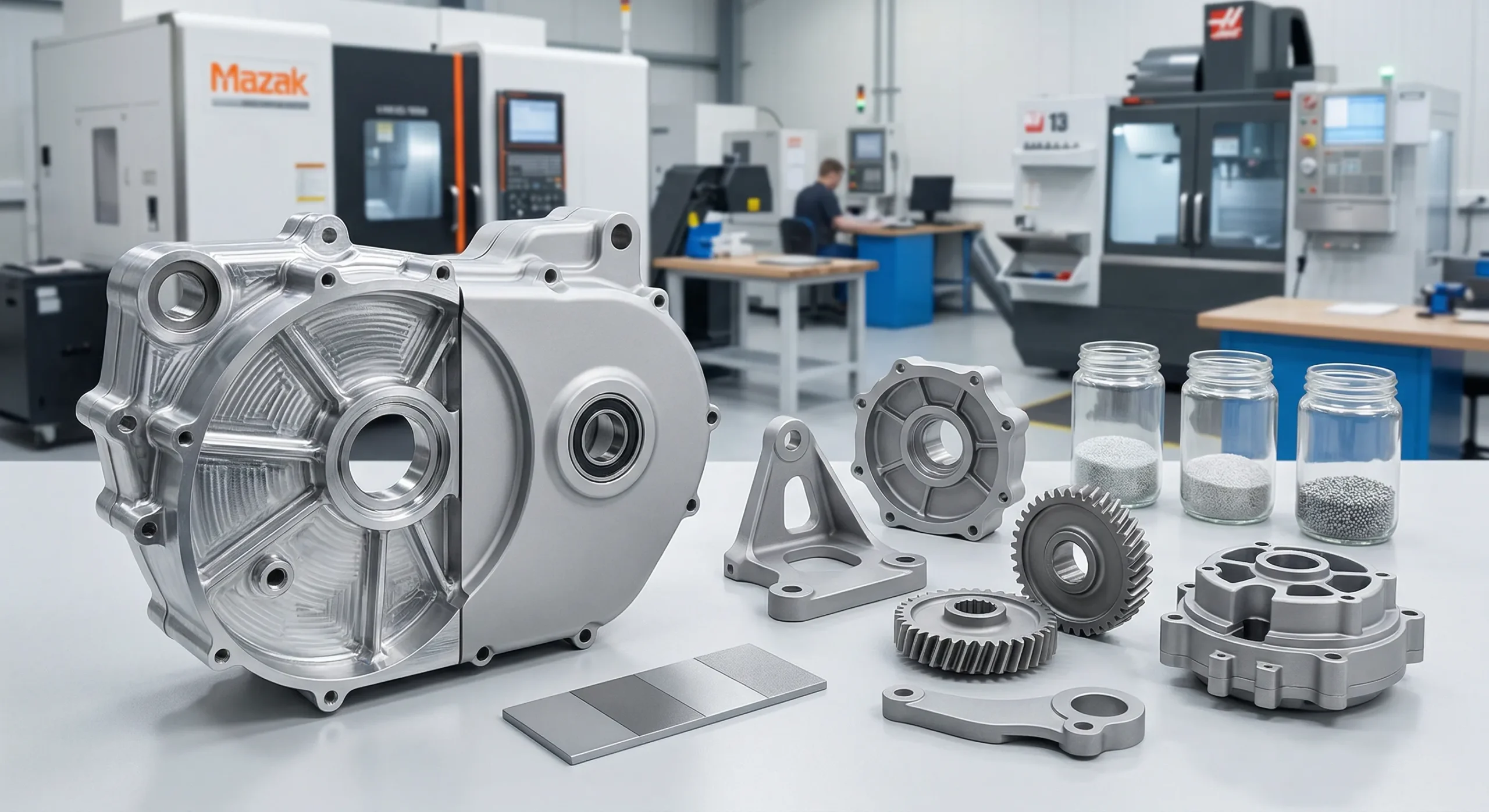
High-accuracy external & internal spur gears, gear shafts, racks, and anti-backlash sets — manufactured to DIN / AGMA standards. Module 0.5–20 (metric or inch diametral pitch), any tooth count, prototype to mass production with full CMM inspection.
External, internal, gear shafts, racks, anti-backlash sets, micro, hubless — any spur gear configuration your design calls for, in any quantity from one prototype to 50,000-piece production.
External Spur Gears
The standard configuration — involute teeth cut on the outer cylinder. The most efficient gear type for parallel-shaft transmission. Module 0.5–20, any tooth count, in steel, aluminum, brass, or plastic.
External ToothDIN 4–12
Internal Spur Gears
Ring gears with teeth cut on the inside — essential for planetary gearboxes, integrated hubs, and compact reductions. Cut by gear shaping or wire EDM where hobbing cannot reach.
Ring / AnnularPlanetary
Spur Gear Shafts
Spur gear and shaft machined as a single part for maximum concentricity (TIR ≤ 0.008 mm). The standard choice for motor pinions, servo drives, and high-torque idlers — eliminates keyway slack.
Integrated ShaftTurn-Mill
Anti-Backlash & Zero-Backlash Gears
Split spring-loaded designs or precision-ground pairs with sub-arcminute lash. For positioning systems, servo actuators, optical instruments, and indexing tables.
Split / SpringServo
Gear Racks & Rack-and-Pinion Sets
Straight spur gear racks paired with matching pinions for rotary-to-linear motion conversion. Ground and hardened options for CNC linear drives, gantries, and lifting systems.
Linear MotionGround
Micro & Miniature Spur Gears
From 0.5 module upward for medical devices, optical instruments, and consumer electronics. Custom small brass spur gears, stainless, or POM with any tooth count from 8 teeth.
M 0.3–1.0Instruments
Large Diameter Spur Gears
Outside diameter up to 600 mm for heavy industrial gearboxes, mining equipment, and slow-speed power transmission. Hobbed, ground, or carburized to spec. Large plastic spur gears also available.
OD ≤ 600mmHeavy Duty
Hubless & Double (Cluster) Spur Gears
Hubless spur gears save weight and axial space. Double spur gears combine two tooth counts on one blank for compact 2-stage reductions in tight envelopes.
Weight Save2-Stage
Technical Specs
Gear Machining Capabilities
Four spur gear cutting methods — from standard hobbed production gears to ultra-precision ground aerospace components.
⚙️
Gear Hobbing
High-volume
🔬
Gear Grinding
Ultra-precision
🏭
5-Axis Milling
Complex geometry
🔧
Turn-Mill
Shaft gears
Spur Gear Hobbing
CNC hobbing machines deliver consistent involute tooth profiles across large batches. The fastest, most economical method for manufacturing standard external spur gears, spur gear shafts, and metric or inch profiles in steel, aluminum, and brass.
Module range
0.8 – 16 mm
Max OD
600 mm
Max face width
300 mm
Quality grade
DIN 6–9 standard
Profile tolerance
±0.010 mm
Typical quantity
100 – 50,000 pcs
Lead time
7 – 14 days
Materials
Steel, Al, Brass
Spur Gear Grinding
Post-hobbing or post-hardening grinding for aerospace and precision instrument gears. Ground spur gears achieve DIN 4–5 and Ra ≤ 0.4 µm — the standard finishing process for hardened spur gears, anti-backlash pairs, and zero-backlash positioning applications.
Module range
0.5 – 10 mm
Max OD
320 mm
Quality grade
DIN 4–6 precision
Profile tolerance
±0.005 mm
Surface finish Ra
0.2 – 0.8 µm
Post heat treatment
Yes — hardened grinding
Lead time
10 – 18 days
Materials
20CrMnTi, 42CrMo4, M2
5-Axis CNC Spur Gear Machining
CNC spur gear machining with integrated hubs, flanges, internal teeth, or split designs — all in one setup. The go-to process for prototypes, custom internal spur gears, anti-backlash and hubless designs, and short-run production where tooling cost matters.
Module range
1 – 20 mm
Max OD
500 mm
Quality grade
DIN 7–9
Profile tolerance
±0.015 mm
Integrated features
Bores, keyways, hubs
MOQ
1 pc
Lead time (proto)
5 – 10 days
Materials
All metals + plastics
Turn-Mill Compound (Spur Gear Shafts)
Shaft-mounted spur gears and pinion shafts completed in one setup for maximum concentricity. Ideal for customized spur gear shaft assemblies, integrated keyways and splines, and any spur gear with shaft that needs tight runout control.
Max turning dia.
280 mm
Max shaft length
800 mm
Concentricity
≤ 0.008 mm TIR
Profile tolerance
±0.010 mm
Keyway / spline
Yes — inline
Lead time
7 – 14 days
Materials
Steel, Stainless, Alloy
Materials
50+ Certified Materials
Full mill certificates and spectral analysis on every batch — steel, stainless, brass, bronze, aluminum, and engineering plastics.
Metals
Engineering Plastics
20CrMnTi Steel
Case-hardened, HRC 58–62 surface, tough core. The default for hardened spur gears in automotive transmissions.
High LoadHardenedAutomotive
42CrMo4 Carbon Alloy Steel
Through-hardened, excellent fatigue resistance. Standard carbon steel spur gear material for heavy industrial drives.
Heavy DutyIndustrial
Al 6061-T6 / 7075
Lightweight aluminum spur gears, anodizable. Aerospace actuators and precision instruments.
LightweightAnodizable
C36000 Brass
Free-machining brass spur gears, low-noise, corrosion-resistant. Ideal for small brass spur gears in clocks and instruments.
Low NoiseCorrosion-Res.
Phosphor Bronze
Self-lubricating against steel mate, excellent wear life. Standard for bronze spur gears paired with worm or low-speed steel pinions.
Self-LubricatingWear-Res.
SUS304 / 316L Stainless
Food-grade and medical-grade stainless steel spur gears. Sterilizable, fully corrosion-resistant.
Food GradeMedical
POM (Delrin / Acetal)
Self-lubricating, low friction, dimensionally stable. The default plastic spur gear material — delrin spur gears in stock, fully CNC-machined.
Chemical-resistant, rated to 260°C. Sterilizable for surgical and lab instrument drives.
High TempChemical Res.
Phenolic Laminate
Quiet-running phenolic spur gears, water-resistant, electrically insulating. Pairs well with steel mate in pumps and small motors.
QuietElectrical Iso.
Polyurethane (TPU)
Tough polyurethane spur gears with shock damping. Suitable for intermittent-load drives in textile and packaging machines.
Shock Damp.Tough
Reference
Spur Gear Standard Specifications
Module, pressure angle, diametral pitch, tolerance — the standard specifications every spur gear drawing should define. A working reference for engineers and procurement teams preparing CAD or RFQs.
📏Spur Gear Module Chart (Metric)
Module (m) is the metric measure of tooth size — pitch diameter divided by tooth count. Standard module series per ISO 54 / DIN 780:
Series I (preferred)
Series II
Typical Use
0.5, 0.8, 1, 1.25, 1.5
0.55, 0.7, 0.9, 1.125, 1.375
Miniature, instruments, 0.5 module spur gear
2, 2.5, 3, 4, 5
1.75, 2.25, 2.75, 3.5, 4.5
General industrial (module 2, 3, 4 spur gear)
6, 8, 10, 12, 16, 20
5.5, 7, 9, 11, 14, 18
Heavy machinery, large industrial
⊕Diametral Pitch (Inch System)
For inch spur gears, diametral pitch (DP) defines tooth size — the number of teeth per inch of pitch diameter. Common spur gear diametral pitches and metric module equivalents:
DP
Module (mm)
Typical Use
20, 24, 32, 48
1.27 → 0.53
Instruments, model gears
10, 12, 16
2.54 → 1.59
Robotics, small machines
5, 6, 8
5.08 → 3.18
Industrial gearboxes
2, 2.5, 3, 4
12.7 → 6.35
Heavy industrial
∠Standard Pressure Angles
The pressure angle (α) defines tooth flank geometry. 20° is the global standard pressure angle for spur gears. 14.5° survives in legacy equipment; 25° is used for higher load capacity:
Pressure Angle
Status
Notes
20°
Standard
Default for new gears, ISO & AGMA
14.5°
Legacy
Pre-1960 imperial, quieter but weaker
25°
High load
Min. 13 teeth, higher capacity
ƒKey Spur Gear Formulas
Pitch diameter (d) — the imaginary circle where two meshing involute spur gears effectively contact. The single most important dimension on any spur gear drawing:
d = m × z (metric) · d = z / DP (inch)
Center distance for two meshing spur gears:
a = (d₁ + d₂) / 2 = m × (z₁ + z₂) / 2
Outside diameter: da = m × (z + 2) · Tooth thickness at pitch line: s = π × m / 2 · Recommended face width: b = 8 × m to 12 × m
✓Quality Grades & Tolerance (DIN / AGMA)
Quality class controls profile, helix, pitch, and runout deviation — also driving spur gear center distance tolerance. Lower number = higher precision. Standard mapping per DIN 3961–3967 / AGMA 2015:
DIN Class
AGMA
Application
4 – 5
13 – 12
Aerospace, measurement equipment
6 – 7
11 – 10
Precision robotics, servo drives
8 – 9
9 – 8
Industrial gearboxes (standard)
10 – 12
7 – 5
Commercial, low-speed
📐Spur Gear Engineering Drawing Checklist
A complete spur gear drawing should specify the parameters below. Missing items will delay quoting while we clarify dimensions and tooth geometry:
• Module (m) or Diametral Pitch (DP)
Required
• Number of teeth (z)
Required
• Pressure angle (default 20°)
Required
• Face width (b)
Required
• Pitch / outside / root diameter
Required
• Quality grade (DIN or AGMA)
Required
• Tooth thickness / backlash
Recommended
• Profile / lead modifications
For DIN ≤ 5
• Material, heat treatment, surface finish
Required
Case Studies
Real Projects, Real Results
Selected orders showcasing our range — from single prototypes to 10,000+ production runs.
Automotive
Transmission Idler Spur Gear Set
Material
20CrMnTi
Process
Hob + Grind
Quantity
2,000 pcs
Lead Time
12 days
✓ 100% passed German TÜV incoming inspection
Robotics
Robot Joint Drive Gears (POM)
Material
POM Delrin
Process
5-Axis CNC
Quantity
200 pcs
Lead Time
5 days
✓ Zero rejects · scaled to 5,000 pc production run
Aerospace
Aerospace Actuator Spur Gear
Material
Al 7075-T6
Process
5-Axis + Anodize
Quantity
50 pcs
Grade
DIN 5
✓ FAI approved in 1 cycle · full CMM report enclosed
How It Works
From Drawing to Your Door
Upload your CAD file — we handle everything from DFM to final inspection and shipping.
01
Upload CAD / Drawing
DXF, DWG, STEP, IGES or PDF spur gear engineering drawings. Drag & drop or email to our engineers.
02
Quote in 48 Hours
Process recommendation, material options, and firm lead time with cost breakdown.
03
Production & CMM QC
Spur gear machining with in-process Klingelnberg measurement and full FAI report.
Every spur gear leaving our Chinese precision machining facility passes a 4-stage inspection protocol before it ships.
Certifications & Equipment
✓
ISO 9001:2015
Quality Management System — all processes certified
📐
DIN / AGMA Standards
DIN 3961–3967 tolerance classes 4–12 available · AGMA 2015 compliant
🔭
Zeiss CMM + Klingelnberg
Imported 3D coordinate & dedicated gear measurement systems
📄
Full Material Certification
Mill cert + spectral analysis on every material batch
4-Stage Inspection Protocol
1
Incoming Material Check
Spectral analyzer verifies alloy grade before any machining begins.
2
First Article Inspection
Full CMM measurement of the first part — all critical dimensions confirmed before batch production.
3
In-Process Gear Measurement
Klingelnberg center checks profile, helix, pitch deviation and runout during production.
4
Final Outgoing Inspection
100% visual + sampled CMM. Full measurement report shipped with every order.
Reviews
Trusted by Engineers Worldwide
★★★★★
"500 pcs of 20CrMnTi spur gears for our gearbox assembly. Dimensional report was pristine — every gear passed incoming inspection first time. Lead time 12 days, exactly as quoted."
MK
Marcus K.
Drive Systems Engineer · Germany
★★★★★
"Prototype POM gears arrived in 5 days. Tooth profile matched the drawing exactly. Scaled to 5,000 pc production run with zero issues. HXC is now our sole supplier for plastic gears."
SR
Sophie R.
Robotics Lead Engineer · France
★★★★★
"Aerospace-grade aluminum gears to DIN 6. CMM report was detailed, surface finish exceeded spec. Passed TÜV audit without a single NCR. On-time delivery every order."
JT
James T.
Procurement Manager · USA
FAQ
Frequently Asked Questions
Everything engineers and buyers ask about spur gears — answered by our manufacturing team.
A spur gear is the simplest and most common type of cylindrical gear. It has straight teeth cut parallel to the gear's rotational axis, and meshes with other gears in the same plane to transmit power between parallel shafts. Spur gears are widely used because they are easy to manufacture, highly efficient (97–99%), and available in a vast range of sizes and materials.
Look for three key features: (1) straight teeth that run perfectly parallel to the shaft axis — not angled or twisted; (2) a cylindrical body (not conical or worm-shaped); and (3) external or internal tooth profiles on a flat disc. If you view the gear face-on, the teeth appear as straight radial lines. Helical gears look similar but their teeth are visibly angled.
Per ISO 54 / DIN 780, the preferred standard modules for spur gears are: 0.5, 0.8, 1, 1.25, 1.5, 2, 2.5, 3, 4, 5, 6, 8, 10, 12, 16, 20 (Series I). Module 1 to 3 covers most robotics and small industrial applications; module 4 to 6 dominates automotive and machine-tool gearboxes; module 8 and above are used in heavy industrial drives. Module is calculated as pitch diameter divided by tooth count (m = d / z). HXC machines spur gears across the full metric module range plus inch-system diametral pitches from DP 2 to DP 48.
For metric spur gears: d = m × z — pitch diameter equals module multiplied by tooth count. Example: a 24-tooth gear with module 2 has a pitch diameter of 48 mm. For inch spur gears: d = z / DP — tooth count divided by diametral pitch. Example: 48 teeth at DP 16 = 3 inch pitch diameter. Pitch diameter defines where two meshing gears effectively contact and is the single most critical dimension on a spur gear engineering drawing. Center distance between two meshing spur gears equals (d₁ + d₂) / 2.
Spur gears appear in almost every industry: automotive (transmission idler gears, window lift motors), medical (surgical robots, infusion pumps), aerospace (actuator drives), robotics (servo gearheads), industrial machinery (pumps, compressors, rack-and-pinion linear drives), and consumer electronics (camera autofocus mechanisms, printers). They are the default choice whenever parallel-shaft power transmission is needed at moderate speeds.
"Regular gear" is not a technical term — in engineering, spur gear is itself the baseline gear type. Other gear families (helical, bevel, worm, planetary) are defined by how they differ from spur gears. Compared to helical gears, spur gears have straight teeth and generate no axial thrust force; compared to bevel gears, they work on parallel rather than intersecting shafts; compared to worm gears, they are reversible and far more efficient.
Spur gears are also called straight-cut gears or straight gears, referring to the orientation of their teeth. In racing and performance automotive contexts you will often hear "straight-cut gearbox," meaning a transmission built with spur (not helical) gears. In some older technical literature they are simply called cylindrical gears, though today that term covers both spur and helical variants.
The main advantages are: high efficiency (97–99% per mesh — no axial thrust losses); simplicity — the easiest gear type to design, manufacture, and inspect; low cost — hobbing is fast and economical at any volume; no axial load on bearings, simplifying shaft and housing design; precise speed ratios — suitable for positioning and indexing applications; and wide material choice — from hardened steel to engineering plastics.
The main limitations are: noise at high speed — tooth engagement is an impact, not a gradual mesh, producing a characteristic whine above ~3 m/s pitch-line velocity; lower load capacity per unit width compared to helical gears (contact is a line rather than a diagonal band); parallel shafts only — cannot transmit power between non-parallel axes; and vibration from the same impact engagement that causes noise. For high-speed, low-noise applications, helical gears are generally preferred.
At low to moderate speeds they are quiet; at high speeds they produce a distinctive whine because all tooth contact starts and ends simultaneously — an impact rather than a gradual engagement. Noise increases with pitch-line velocity, tooth error, and backlash. To reduce noise: use profile grinding to DIN 5–6, apply tip relief or crowning, choose POM or nylon for light-duty applications, and ensure precise alignment. Helical gears are inherently quieter at high speed due to overlapping tooth contact.
Yes — spur gears are generally the most economical gear type to manufacture. Gear hobbing is fast and requires no special tooling per profile; one hob covers a range of tooth counts at the same module. CNC hobbing can produce hundreds of gears per hour in production. Cost drivers are material grade (alloy steel vs. stainless), required DIN accuracy class (each class step roughly doubles finishing time), and order quantity. At HXC, prototype quantities start from a competitive per-piece price with no tooling fee.
20° is the global standard pressure angle for spur gears today and is used in over 95% of new designs. It offers the best balance of load capacity, contact ratio, and minimum tooth count (17 teeth before undercutting). 14.5° remains in older imperial drive trains and pre-1960 equipment — quieter but weaker and harder to source replacement cutters for. 25° is used where high load capacity is needed and where as few as 13 teeth are acceptable without undercutting. All HXC spur gears are 20° pressure angle by default; 14.5° and 25° are available on request.
External spur gears have teeth on the outside of a cylinder and mesh with another external gear — the rotation direction reverses between input and output. Internal (annular) spur gears have teeth cut on the inside of a ring and mesh with an external pinion sitting inside them — the rotation direction stays the same and the meshing gears share axial space, giving a more compact design. Internal gears are essential for planetary gearboxes, integrated wheel hubs, and harmonic drives. They cannot be hobbed and must be made by gear shaping, broaching, or wire EDM, which makes them more expensive but irreplaceable for compact reduction systems.
Yes. "Straight-cut" is the defining characteristic of spur gears — their teeth are machined parallel to the gear's rotational axis, giving a perfectly straight tooth profile when viewed from the side. This is what distinguishes them from helical gears (angled teeth), herringbone gears (double-angled), and spiral bevel gears (curved). The straight cut is also why they generate an impulsive engagement and no axial thrust.
Yes — all gears have teeth by definition, and spur gears are no exception. Their teeth have an involute profile: a mathematically precise curve that ensures a constant velocity ratio regardless of slight center-distance variations. The key parameters are module (tooth size, metric standard), pressure angle (typically 20°), and tooth count. Tooth count divided by module gives the pitch diameter. HXC machines spur gears from module 0.5 (micro gears) to module 20 (large industrial gears).
For the same tooth size and face width, helical gears typically carry 20–40% more load than spur gears, because the diagonal tooth contact distributes load over a longer contact line. However, helical gears generate axial thrust forces that must be absorbed by bearings, adding complexity and cost. For moderate loads, the strength advantage of helical gears is rarely needed and spur gears are the practical choice.
Spur gears are better when: cost, simplicity, and efficiency matter most; speed is low to moderate; axial space is limited; or you need no thrust loads on bearings. Helical gears are better when: operation is at high speed (above ~3 m/s pitch velocity); low noise is critical; or you need higher load capacity in the same envelope. In practice, most industrial and automotive gearboxes use helical gears for main stages and spur gears for ancillary drives, idlers, and instrument mechanisms.
For maximum strength, case-hardened alloy steels are the standard choice: 20CrMnTi (carburized to HRC 58–62) and 42CrMo4 (through-hardened to HRC 50–55) dominate automotive and industrial gearing. For very high contact stress, M2 tool steel ground to DIN 4 gives the highest surface hardness. For corrosive environments, SUS316L stainless trades some strength for corrosion immunity. Grade 5 titanium offers the best strength-to-weight ratio for aerospace. Engineering plastics (PEEK, POM) are strongest among non-metallic options.
Worm gears are self-locking when the worm lead angle is less than the friction angle — typically below about 5°. At low lead angles, the reaction force on the worm tooth is directed more into the thread flanks than along the thread, so friction prevents the wheel from rotating the worm backward. This is why worm gear lifts and door locks hold position with no brake. Spur and helical gears can always be back-driven because their tooth normals are nearly perpendicular to the shaft, creating low friction relative to the driving force.
The 17-tooth rule states that a standard 20° pressure-angle spur gear must have at least 17 teeth to avoid undercutting — a condition where the cutting tool removes material from the base of the tooth, weakening it and distorting the involute profile. Below 17 teeth, the tooth root is notched, reducing bending strength and contact ratio. Solutions for fewer teeth include: profile shifting (moving the rack cutter outward), using a higher pressure angle (25° allows as few as 13 teeth), or stub tooth profiles. HXC's engineers can advise on the optimal approach for your pinion design.
Six proven approaches: (1) Higher accuracy class — grinding to DIN 5 or 6 reduces tooth error and impact; (2) Tip relief — a small chamfer at the tooth tip eases engagement; (3) Crowning — a slight barrel shape on the tooth face reduces edge loading; (4) Plastic mating gear — pairing a steel driver with a POM or nylon driven gear damps noise significantly; (5) Increased contact ratio — more teeth in simultaneous contact (achieved by larger module or addendum modification) smooths transmission; (6) Lubrication and alignment — correct oil viscosity and precise shaft alignment eliminate most noise in well-designed spur gear pairs.
Get a Quote
Send Your Drawing. Get a Quote.
Every enquiry includes a DFM review — tolerance feasibility, material confirmation, and process approach confirmed before production starts. MOQ 1 piece.
24hr
Quote Response
MOQ 1
Prototypes OK
ISO
9001:2015
📐
DFM Review on Every Enquiry
Tolerance feasibility, fixturing strategy, and material confirmation. Specific, actionable feedback — not generic pushback.
🎯
First Article Inspection — Standard
FAI report on every new run. Material certs and surface treatment certs included with every shipment.
🔄
Same Process: Prototype to Production
Process plan from your prototype applies to production batches. No re-qualification when you scale.
⚙
3 / 4 / 5-Axis CNC + Turning
Complex structural parts, shafts, housings, and transmission components. Metals and engineering plastics.
ISO 9001:20153/4/5-Axis MillingCNC TurningCMM InspectionGlobal Delivery