Custom flex splines, circular splines, wave generators, and output flanges. Wall thickness ≥ 0.3 mm,
tooth profile tolerance ±0.003 mm, IT5 bores — all in one 5-axis setup. Prototype to production for
collaborative and industrial robots.
Bearing bore tolerance class wave generator & output flange
0.3mm
Minimum flex spline wall thickness achieved
7 Days
Fastest prototype delivery 1–5 pc sample orders
Why It's Difficult
Harmonic Reducer Machining Challenges
Harmonic reducer components combine three conflicting demands in a single part: ultra-thin flexible walls,
micron-level tooth accuracy, and precision bearing interfaces — all concentric within a few micrometres.
🌀
Flex Spline Thin-Wall Machining
The flex spline is a thin-walled cup or hat that must deflect elastically during operation. Wall thickness
as low as 0.3 mm must be held without chatter or distortion — requiring custom fixturing, optimised
cutting parameters, and vibration-damping toolpaths on a 5-axis centre.
⚙️
Involute Tooth Profile Accuracy
Harmonic drive teeth are fine-pitch involute profiles cut into a thin flexible wall. Profile tolerance
±0.003 mm and pitch error ≤ 0.004 mm are required to achieve the near-zero backlash (≤ 1 arc-min) that
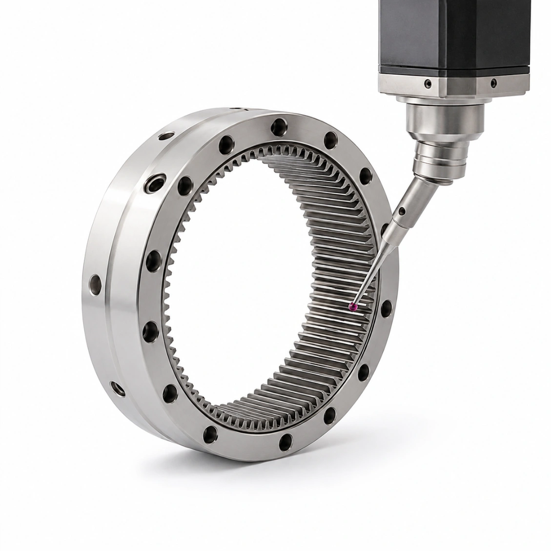
robot joints demand. All profiles are verified on our Zeiss CMM with optical tooth scanning.
⦿
Concentricity Stack-Up
Circular spline bore, wave generator bearing seat, and output flange pilot must all be concentric within
≤ 0.005 mm to ensure zero preload variation across the flex spline engagement zone. All critical features
are machined in a single setup to eliminate re-chucking error.
Our Work
Harmonic Components We've Made
Flex splines, circular splines, wave generators, and output flanges for collaborative and industrial
robot joints.
Four core harmonic reducer components — each with its own precision demands, machined and inspected to your
drawing.
🌀
Flex Spline (Cup & Hat Types)
Thin-wall, fine-pitch tooth form
OD range
14 – 200 mm
Min. wall thickness
0.3 mm achievable
Tooth count (Z)
50 – 320
Tooth profile tol.
±0.003 mm
Pitch error
≤ 0.004 mm
Spline types
Cup · Hat · Silk-hat
Materials
42CrMoA, 17-4PH, Ti-6Al-4V
Lead time (proto)
7 – 12 days
⭕
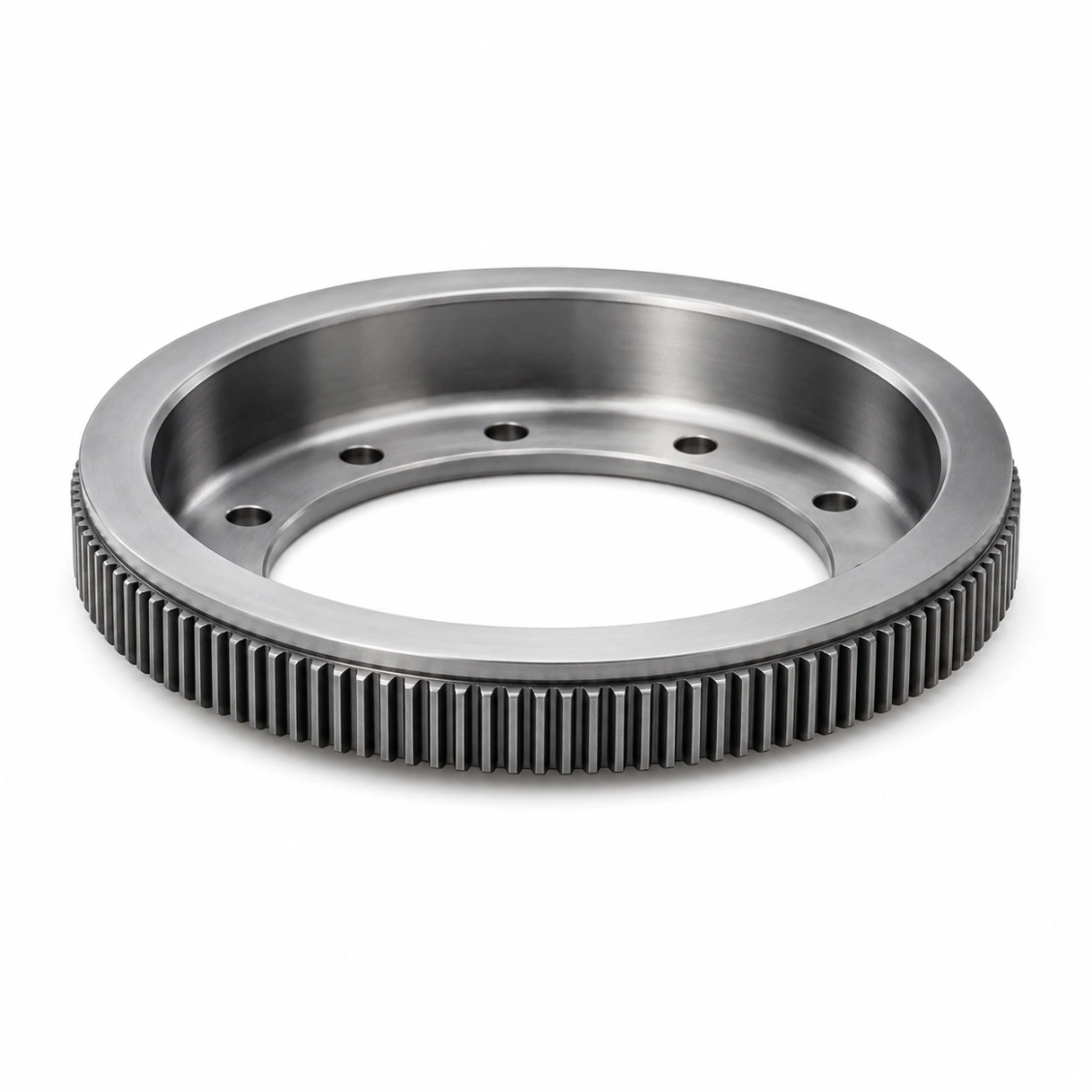
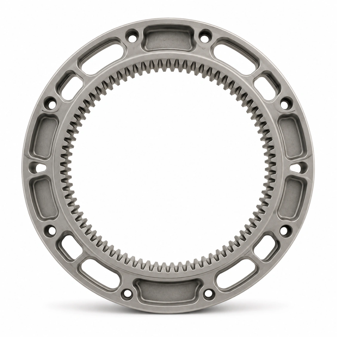
Circular Spline (Ring Gear)
Internal involute, IT5 bore
OD range
20 – 300 mm
Bore tolerance
IT5 standard
Tooth count (Z)
52 – 322 (Z+2 vs flex)
Tooth profile tol.
±0.003 mm
Concentricity
≤ 0.005 mm TIR
Face runout
≤ 0.005 mm
Materials
42CrMo4, M2 HSS, SUS440C
Lead time (proto)
7 – 12 days
🔵
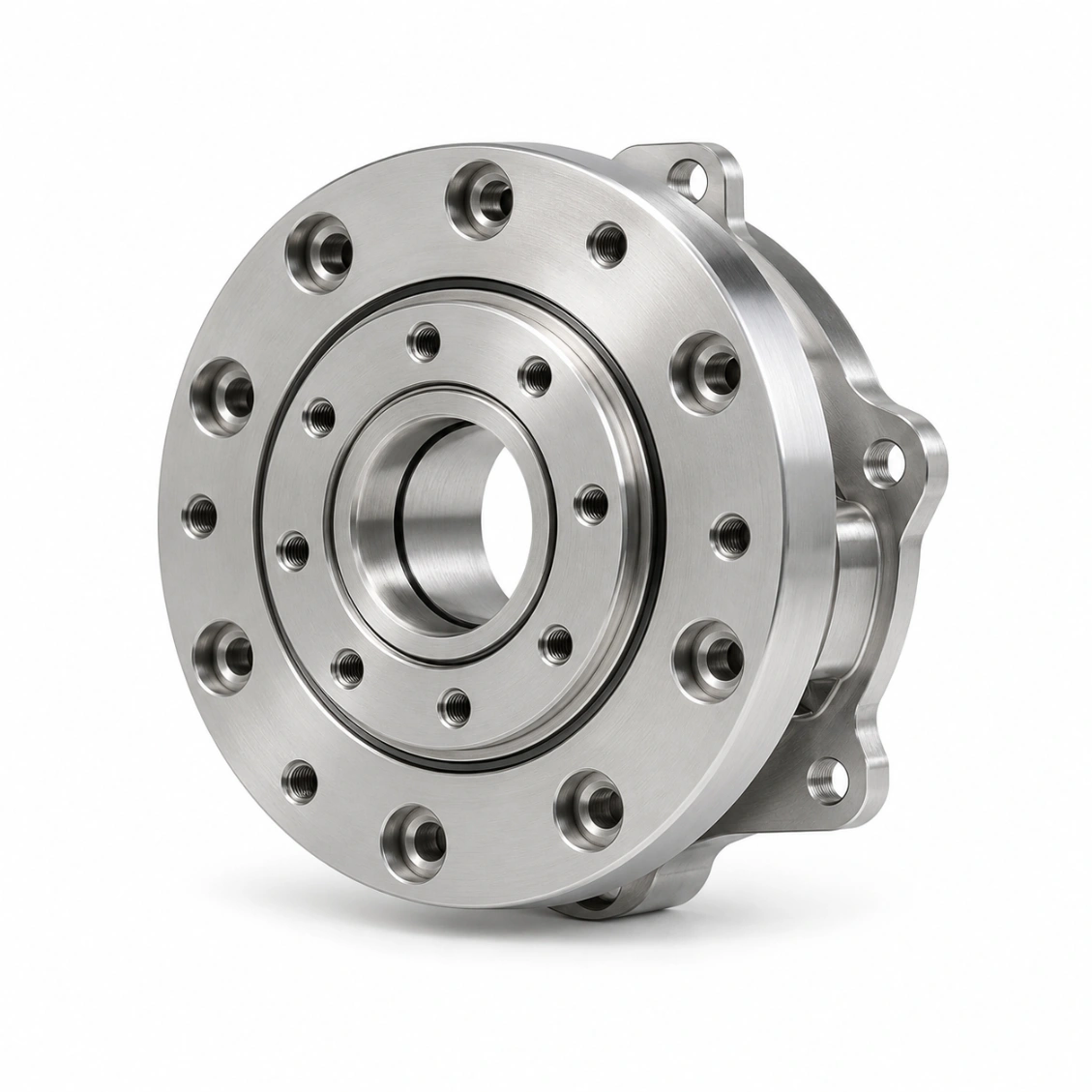
Wave Generator (Cam & Bearing)
Elliptical cam, IT5 shaft bore
OD range
12 – 180 mm
Ellipse ratio
Per drawing / Harmonic catalogue
Shaft bore tol.
IT5 · H5 / K5
Cam profile tol.
±0.004 mm
Concentricity
≤ 0.004 mm TIR
Bearing race fit
P5 / P4 thin-section bearing
Materials
52100 Bearing steel, 40Cr, Ti
Lead time (proto)
7 – 14 days
🔩
Output Flange & Cross-Roller Interface
Pilot bore, bolt pattern, face runout
OD range
20 – 350 mm
Pilot bore tol.
IT5 · H5
Face runout
≤ 0.005 mm
Bolt PCD pos. tol.
±0.010 mm
Cross-roller seat
Yes — inner/outer race
Concentricity
≤ 0.005 mm bore-to-pilot
Materials
Al 7075, SUS316L, 42CrMo4
Lead time (proto)
5 – 10 days
How It Works
From Drawing to Finished Part
Upload your 2D/3D file — receive DFM feedback, wall-thickness analysis, and a confirmed quote within 48
hours.
01
Upload Drawing
STEP, DXF, PDF or sketch. Harmonic Drive model number accepted as reference.
02
DFM Review & Quote
Free thin-wall feasibility check, material and heat treatment recommendation, and firm lead time — within 48 hours.
03
5-Axis Machining & CMM
All critical features in one setup. Optical tooth profile scan and full CMM dimensional report on every part.
04
Ship Worldwide
Individual packaging to protect flex spline walls. CMM report and material certs enclosed. DHL / FedEx / sea freight.
Reviews
Trusted by Robot Engineers Worldwide
★★★★★
"Cup flex splines with 0.4 mm wall — we'd been rejected by three other suppliers. HXC delivered 30 pcs within spec on the first attempt. CMM report confirmed every tooth profile within ±0.003 mm. Remarkable."
FW
Felix W.
Robotics Engineer · Switzerland
★★★★★
"HXC's DFM review identified a stress concentration at the cup bottom radius that would have caused fatigue failure in production. They proposed a fillet change that increased fatigue life by an estimated 40%. Partners, not just a supplier."
YM
Yuki M.
Chief Mechanical Engineer · Japan
★★★★★
"Production batch of 200 circular splines. Statistical CMM sampling showed Cpk > 1.67 on all critical dimensions across the entire batch. This level of process consistency is exactly what our production line needs."
RB
Rachel B.
Supply Chain Engineer · USA
FAQ
Harmonic Reducer Components — FAQ
Common questions from robotics engineers and procurement teams — answered by our manufacturing team.
A harmonic drive (strain wave gear) is a precision speed reducer consisting of three core components: the wave generator (an elliptical cam with a thin-section bearing), the flex spline (a thin-walled cup or hat with external teeth that elastically deforms around the wave generator), and the circular spline (a rigid ring with internal teeth, 2 more than the flex spline). As the wave generator rotates, the flex spline teeth engage the circular spline teeth at two points, producing a very high reduction ratio — typically 30:1 to 160:1 — with near-zero backlash and high torque density.
The flex spline is a thin-walled, cup-shaped or hat-shaped component with fine-pitch involute teeth on its outer circumference. It must be stiff enough to transmit torque yet flexible enough to deflect elastically into an elliptical shape under the wave generator. Wall thickness is typically 0.3–0.8 mm. Machining challenges include: workpiece deflection under cutting forces (requiring custom fixtures and low-force toolpaths); chatter from thin wall resonance; and achieving ±0.003 mm tooth profile accuracy while the part is so compliant it deforms under measuring probe force. HXC uses vibration-damping fixtures, trochoidal milling, and corrected CMM measuring force to address all three.
Flex splines experience high cyclic bending stress and require excellent fatigue life. The industry standard is 42CrMoA (4140 equivalent) hardened to HRC 38–42 — it combines high yield strength (~1,000 MPa) with good fatigue performance and machinability. For aerospace and weight-critical applications, 17-4PH stainless steel (H900 condition) offers similar strength with better corrosion resistance. Ti-6Al-4V is used where minimum weight is the priority, despite its lower elastic modulus — the flex angle geometry must be adjusted. Standard 42CrMo4 is not recommended as it has lower fatigue life than 42CrMoA under cyclic bending.
The three flex spline forms define how the spline is mounted and its axial length: Cup (C) type — the most common; a deep cup with teeth near the open end and a mounting flange at the closed end. Provides high torsional stiffness but requires axial depth. Hat (F) type — a shallow hat shape where the mounting flange is at the tooth end; allows shorter overall assembly length (pancake harmonic drives). Silk-hat (S) type — an extended hat with a large output flange diameter; maximises output flange stiffness for large hollow-bore harmonic drives used in robot wrists. HXC machines all three types.
Standard harmonic drives use a modified involute tooth profile — not a standard gear tooth — with a reduced pressure angle (typically 20° but modified) and an addendum/dedendum ratio optimised for the large deflection of the flex spline. The exact profile is defined by the harmonic drive manufacturer (Harmonic Drive SE, HDSI, Ovalo, Spinea, etc.) and is specified on the component drawing. HXC machines to the customer's profile drawing using 5-axis simultaneous tooth form milling or gear shaping followed by CMM optical profile verification. We do not reverse-engineer competitor tooth profiles — a customer drawing or approved profile data is required.
Harmonic drives achieve near-zero backlash — typically ≤ 1 arc-minute in a correctly assembled unit, compared to 3–10 arc-minutes for a precision planetary gearhead. This is the fundamental advantage driving their use in robot joints. Achieving ≤ 1 arc-minute requires: flex spline tooth profile tolerance ±0.003 mm; circular spline tooth profile ±0.003 mm; wave generator cam profile ±0.004 mm; and concentricity of all three components ≤ 0.005 mm TIR. HXC verifies all four parameters on the CMM and includes the data in the measurement report.
Wall thickness at the tooth root — the thinnest and most critical point — is measured using 3D CMM stylus scanning with a ruby ball tip diameter matched to the root radius. The CMM program maps the outer tooth-root surface and the inner bore surface and calculates the minimum wall at each measured tooth. For very thin walls (≤ 0.4 mm), a non-contact optical CMM measurement with reduced probe force is used to avoid deflecting the part under measurement. All wall measurements are reported in the dimensional inspection report shipped with each order.
The circular spline is a rigid ring gear that must withstand the contact stress from the flex spline tooth engagement. It is typically harder than the flex spline to ensure the flex spline teeth wear preferentially (the flex spline is the more expensive and difficult-to-replace component). Standard choices: 42CrMo4 through-hardened to HRC 48–52 — the most common industrial choice; M2 HSS hardened to HRC 60–62 — for maximum tooth life in high-cycle applications; SUS440C stainless at HRC 56–58 — for corrosive environments; and Nitrided 38CrMoAl — for very high surface hardness with minimum distortion.
The wave generator consists of an elliptical cam with a thin-section ball bearing pressed onto it. The bearing outer race deforms elliptically to match the cam, and this elliptical outer race pushes the flex spline into engagement with the circular spline at two diametrically opposite points. The bearing must therefore be capable of sustained cyclic elliptical deformation — standard deep-groove bearings fail rapidly. Dedicated thin-section harmonic drive bearings (P4 or P5 accuracy class, ABMA/ISO compliance) are used. HXC machines the cam to the bearing manufacturer's specified outer race seat tolerance, typically P4 class, to ensure correct deformation geometry.
Yes, provided the customer supplies a complete engineering drawing of the component — including tooth profile data, tolerances, material, and heat treatment. We do not copy, reverse-engineer, or reproduce proprietary harmonic drive designs without explicit authorisation from the original designer. If you have an existing component that needs to be replicated, our engineering team can help you prepare the necessary drawing from CMM measurement data. We have supplied replacement flex splines, circular splines, and wave generators for robots where the original manufacturer's spares lead time was unacceptable.
Surface treatment choices depend on the component: Flex splines — typically no coating on the tooth form (coating adds thickness variation that alters tooth mesh). Shot peening is applied to improve fatigue life of the cup bottom radius. Circular splines — black oxide for steel versions (minimal dimensional impact <1 µm); passivation for stainless. Wave generators — chrome plating on the cam OD is applied when cam-to-bearing fit requires controlled growth, otherwise left machined. Output flanges — hard anodizing (Type III) for aluminium; passivation for stainless. All coatings are applied after machining to final tolerances, with allowance machined in as required.
The reduction ratio of a harmonic drive is determined entirely by the tooth counts: Ratio = Z_circular / (Z_circular − Z_flex). Since the circular spline always has exactly 2 more teeth than the flex spline, the formula simplifies to: Ratio = Z_circular / 2. A 100-tooth circular spline (98-tooth flex spline) gives a 50:1 ratio. Common ratios range from 30:1 (Z_c=60) to 160:1 (Z_c=320). Higher ratios require more teeth at the same module — either the OD grows or the module shrinks. HXC can machine components for any ratio; provide your required ratio and envelope constraints and we will calculate the optimal tooth count and module.
Provide as many of the following as possible: component type (flex spline / circular spline / wave generator / output flange); OD and bore dimensions; tooth count and module (or pitch); tooth profile drawing or Harmonic Drive model reference; wall thickness (for flex splines); material and required hardness; surface finish and treatment; key tolerances (bore class, concentricity, face runout); and quantity. A STEP file with GD&T annotation is ideal. A Harmonic Drive SE or HDSI model number (e.g., CSF-20-100-2UH) combined with the component name is sufficient to start a quotation.
Lead times depend on component type and complexity: Flex splines (cup/hat) — 7–12 days for 1–5 pcs prototype; 15–25 days for 20–50 pcs batch. Circular splines — 7–12 days prototype; 14–22 days batch. Wave generators — 7–14 days prototype; 14–20 days batch. Output flanges — 5–10 days prototype; 12–18 days batch. Expedited 5-day service is available for single-component prototypes at a premium. For production runs of 100+ pcs, lead time is quoted on a project basis. All lead times run from drawing approval and deposit receipt.
Get a Quote
Send Your Drawing. Get a Quote.
Every enquiry includes a DFM review — tolerance feasibility, material confirmation, and process approach confirmed before production starts. MOQ 1 piece.
24hr
Quote Response
MOQ 1
Prototypes OK
ISO
9001:2015
📐
DFM Review on Every Enquiry
Tolerance feasibility, fixturing strategy, and material confirmation. Specific, actionable feedback — not generic pushback.
🎯
First Article Inspection — Standard
FAI report on every new run. Material certs and surface treatment certs included with every shipment.
🔄
Same Process: Prototype to Production
Process plan from your prototype applies to production batches. No re-qualification when you scale.
⚙
3 / 4 / 5-Axis CNC + Turning
Complex structural parts, shafts, housings, and transmission components. Metals and engineering plastics.
ISO 9001:20153/4/5-Axis MillingCNC TurningCMM InspectionGlobal Delivery